A self-powered battery tester with an EFM32
I like to participate in electroics design contest. Its always interesting to apply skills within a given timeframe, most times also within a given frame of what to do. Many times its also a chance to get your hands on interesting hardware one would never buy otherwise. Most times I have participated so far was because the theme of the contest (or the hardware to be used) gave me the idea for an interesting project - so its most times just an excuse to build something for fun…
The same happened when Energy Micro announced, last september, their EFM32 Giant Gecko design contest. The theme was, as one would expect from Energy Micro, energy efficency. When I read about it, there came two recent events to my mind. First I had, a couple of weeks ago, disassembled a defective car temperature sensor, which left me with a single AA-cell battery holder still lying around. Second, I had many times before (and with an increasing rate) the problem to find whether some particular battery from the child toys in out household still have some energy in them or not. Until then I always I used a cheap multimeter for that which had a “battery measurement” range, but it gave only a number betwen (typically) 20 and 40, and I never knew whether that was supposed to be good or not.
So the idea hat came to my mind was: why not build a proper battery meter which can give real and accurate numbers. That can’t be so complicated! And since the EFM32 is so low-power, why not make it powered from the battery I’m currently measuring? Drawing some additional microamps from it can hardly change the results…
So I applied with this idea (and second one to, but this will be another post), and got accepted for the next round in the contest (only 40 ideas were accepted overall). So some weeks later I got a STK3700 with a EFM32GG on it my mailbox:
A boost converter is important
In the meantime I had looked for a proper boost converter to be used. It had to be able to start from really low voltages (like 0.8V or even lower) because the battery might be really drained. Also, it should have a low supply current (to not drain the battery even more). And last but not least it should come in a package which I can properly solder (so nothing like QFN or so).
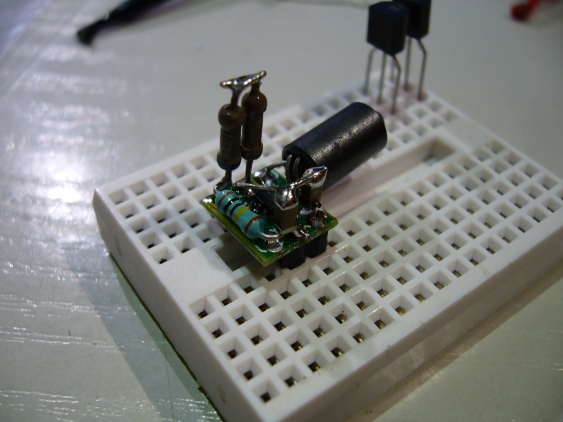
In the end I decided to use the LTC3400 from Linear Technologies. It can start up from voltages as low as 0.85V (guaranteed) while boosting up to 3.3V with a 100mA load (which I don’t need), but can run from as low as 0.5V afterwards. It also came in a nice SOT23-6 package, which made it easy to assemble. Its supply current of 300 µA is not exactly low, but was acceptable. First measurement showed my example could start from voltages as low as even 0.65V under low load, so I was all set.
I build the complete converter around a SOT23 breakout board. The LTC3400 only needs five external components (an inductor, two capacitors and two resistors for setting the output voltage). So it was an easy fit.
Controlled load for proper measuring
Next step was the design for generating a controlled load on the battery. Measuring its voltage without (or with a small load only) doesn’t yield meaningful results. So after studying some literature (aka using Google…) I decided to create two different loads, with about 10 mA and 50 mA current. To switch the current I’m just using 2 NPN transistors which connect an resistor to the battery. This poses 2 problems. First, the load current drops with battery voltage. And the voltage range we are talking about is from 0.8V up to 1.5V, so it is nearly 1:2. And second, the voltage on the resistor is not directly the battery voltage, since there is also the collector-emitter of the transistor. This might be better with a MOSFET, but they typically need higher gate voltages (there are logic-level FETs available for such low voltages, but they are rare and I had none available). So I need to live with a certain inaccuracy regarding the applied load, but since I don’t measure the current but just need it to load the battery I figured it will be OK.
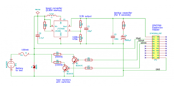
So the final circuit looked like this:
after blowing up one of my LTC3400s by putting a battery the wrong way into the holder, I added an additional reverse polarity protection. It turned out that the battery compartment doesn’t provide clear guidance on how to put the battery in - it just shows the orientation on the lid. So in such cases the diode D1 will conduct, and the fuse F1 will then limit the current.
The other additional component is the backup capacitor C4. It will be charged (slowly) when the whole circuit starts up, with the current limited by R2. Its intention is to serve as backup power reservoir in case the battery cannot stand the load put on it and drops below about 0.5V. Then the charge stored in C4 keeps the whole circuit alive for about 5 seconds.
Since the battery voltage will be lower than the supply voltage (or at least its not higher during voltage rampup), it can be measured directly by the EFM32.
And a battery tester
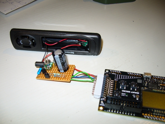
I build everything on a perfboard, as usual, and connected it with a 2-row pin header to the expansion port of the STK3700. Apart from there power supply there only three wires needed - one for measuring the battery voltage and two for controlling the battery load.
The software side itself is simple. The EFM32 starts with a low CPU clock (500kHz) to get low current consumption (about 250µA). After startup it goes to sleep directly, to wait for the battery voltage to stabilize, and for the backup capacitor to fill up. In that mode, it needs about 4µA (EM2 sleep mode). When it wakes up, it measures the battery voltage three times: without load, with 10 and with 50 mA (this is done with oversampling to reduce noise). Then the average of these 3 values is taken, and from I can calculate the approximate remaining battery capacity.
From what I found about the battery discharge curves, I created two discharge curves - one for alkaline and one for NiMH cells. Both have 3 different stages, a steep discharge at the beginning (starting from the voltage when the battery is fresh), followed by a relatively flat discharge plateu in the middle. After reaching nearly the final capacity, the curve gets steep again. So I have 4 points for the curve, each formed by a voltage point together with the capacity value. Given the measured battery voltage, I can use these values to calculate where in the discharge cycle the battery currently is.
After all of this, the measured voltage and the remaining capacity is shown. (The capacity cycles every second between the value for alkaline and NiMH). The EFM32 goes into EM2 sleep mode each time, and wakes up only to cycle between the shown values. The current consumption is low enough to power it for about 5 seconds after removing the battery (most of the current goes into the boost converter anyways, not into the EFM32).
So how did the contest end? Well, I didn’t win, but at least got a honourable mention. According to the feedback I should, for the next contests, try to come up with a PCB for the project instead of building everything on a perfboard. It just looks more professional that way… So gained some experiences, and have a proper battery meter in my toolbox now.


