74 items are tagged with electronics:
Compiling Sigrok and Pulseview on a Beaglebone Black
One of my current projects is to use a BeagleBone Black as logic analyzer. The BeagleLocig project I’m using suggests to transfer the capture files to a PC and use the Pulseview application for viewing. But instead I would like to run Pulseview on the BBB itself, so I can using it directly for configuring the capture process and for viewing the results.
Since it took a while to get the compilation to run through, I want to document the the process.
Continue readingLow-voltage continuity tester
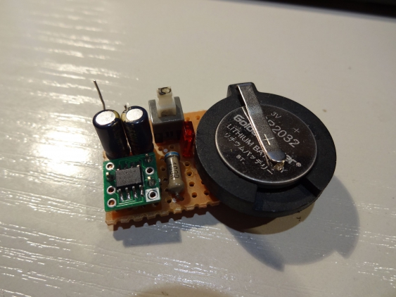
One of the most-often used tools on an electrings workbench, right behind the digital multimeter, is the continuity tester. Whether you want to verify that your solder work was fine, or are looking for a shot where there shouldn’t be one, the continuity tester is the go-to-tool. Turn it on, probe in your circuit and wait for the buzzer to go off. Its as simple as that.
But they most of them share a problem: their probing voltage is too high. They are designed to even turn on a LED, so most meter use a probing voltage of 2 volts, and may go up to 3 V. In my collection only my old and cheap DT-4000ZC uses a probing voltage of 0.44V, all the others are around 2.9V. Why is that a problem, and what can we do about it?
Continue readingStairstep generator with a PSoC4
A while ago I ran across this video from w2aew where he explained using two generators and an integrator to form a stair-step generator. I was intrigued because it seemed like such a simple idea, and a useful one too, but I immediately thought of some improvements. First I wondered why he didn’t implement both generators with 555 timers, and second a voltage buffer on the output seems to be needed.
But then my mind wandered and I realized that the two oscillators were actually PWM generators. And then I it was only a small step to “this can be implemented in a PSoC much better”. So I went ahead and tried it.
Continue readingComparing some oscilloscopes and their probes
Since my review of the TBS1052B-EDU scope I participated in yet another Element14 contest - and part of the provided kits was yet another scope. This time it has been a TBS1202B-EDU, the larger brother of my first scope. So I thought it might be a nice exercise to compare these two scopes with each other. Since this scope comes with 200MHz passive probes (in contrast to the 50MHz probes of the TBS1052B-EDU) I will compare them too. To make it a real shootout (and to even more insight) I will include my iMSO-104 scope too, which has a meager 5MHz analog bandwidth and 12 Msps sample rate.
Continue readingSPG8640-based crystal frequency generator
One of the tools that belong in every electronics toolset is a frequency generator. There are many design out in the internet that to build your own generator. Starting with a simple 555 timer (or even just transistors), moving up to the venerable XR2206 and ICL8038 and then maybe up to the MAX038 they typically can generate since, triangle and square wave over a wide frequency range.
But they all rely on manual frequency setting, and their accuracy is in the single digit percent range (maybe as good as 0.1%). If you want to have a stable frequency source, you need a crystal based oscillator - and that typically means using a DDS chip.
When I needed a small frequency generator for a project several years ago, I did neither had the time nor the skills to build something like that. But I had in my parts box a nice chip that seemed perfect for a small tool - the SPG8640BN.
Continue readingBuilding an ATX power supply
Using ATX PSU as basis for a lab power supply is an easy way to get started when building a lab power supply. It solves all the hard parts about wiring the transformer and the voltage regulation stuff, and basically leaves only the wiring. Especially when one needs some high-current PSU, this a nice way to get a simple solution. So I had this on my ‘projects to do’ list for a while (and even started to get some components). So when I stumbled over a nice project by an italian electronics hobbyist I was intrigued. Francesco Truzzi did a great job not only on creating a nice breakout PCB, but also on adding some additional features. So when he offered to send his surplus PCBs to readers of his blog I took my chance.
Continue readingReview - Tektronix TBS1052B-EDU oscilloscope
As part of the Forget me not challenge in the Element14 community, I got an oscilloscope from Farnell to be used as part of the design challenge. Due to a communication mishap it was advertised as being the 200 MHz version, but in the end all participants got a TBS1052B-EDU. Now that I had some time to use it and get some hands-on experience with it, its about time to write a review.
Continue readingwireless power - status update 2
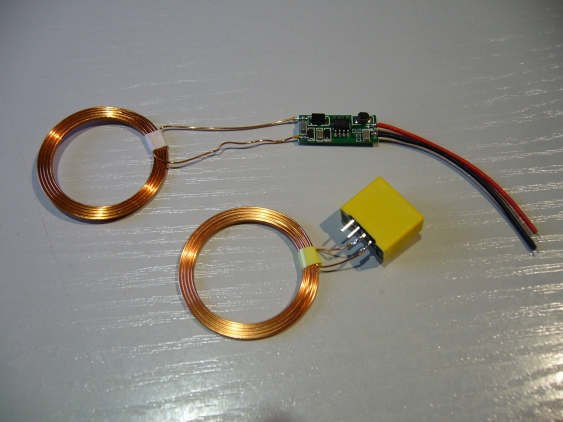
So what happened in the last two weeks? As already mentioned, I finalized the PCB and send it away. I did go with Würth in the end. They were not the cheapest of the lot, but provided the most bang for the buck. I got 5 day manufacturing time (and since they deliver with courier, probably even from Germany, delivery also takes only one day). Also, they did not charge extra for silkscreen or solder resist (as may happen with cheaper manufacturers). And last but not least I got Ni/Au plating for still the same price, which is not only better for long-term usage, but also better than HASL for SMD soldering. So I send the board files off to WEdirekt (no need to convert them to Gerbers), and thanks to Simon Leuz I even got a 10 percent rebate
Continue readingWireless Power - the full schematic explained
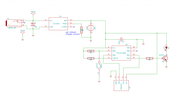
Since the contest is now nearing its completion, I gather its about time to actually show and explain the whole circuit. I already went through some of the parts of it, and how I decided how to build it. But I never showed how these parts work together. So lets have a look.
Continue readingwireless power - status update
So the last couple of weeks was silent with regards to my project - I was just too busy. Being on a business trip left not so much time for doing electronic projects (and I forgot to take the Eagle project with me). And the aftermath was then rather busy at work.
But I got new transmitter coils from Würth in the mean time, and did some experiments with them (which need a write-up).
Apart from that I have finalized my schematic, and added all the missing details I already explained the most important parts of it, but there are still some minor tweaks here and there. So there will be a separate post about it.
Continue readingBuilding a multi-voltage reference for my DMMs
A while ago I saw in the Dangerousprototypes forums a nice project: MrRef. Its a small voltage reference, intended to verify that a digital multimeter is still within its spec. Normally one would use either a real high-precision meter (like the Agilent 3458A) or a really good, calibrated voltage reference. But these are not exactly cheap, and probably overkill for a 50$ (or cheaper) multimeter. So matseng took a not so expensive voltage reference (a MAX6350, but it onto small breakout board, together with 4 batteries, and had something which is at least more accurate than the normal hobbyists multimeter.
Seeing this I did something similar - but I used a REF5020 from TI instead:
but it was not as accurate as I would have liked (the initial accuracy is 0.1%), and the 2.048 Vv output voltage meant that its just over the range for a 2000 counts multimeter (so it read 2.05).
So when I bought a new multimeter last fall (two UT61E actually), I looked into building a new, more accurate reference, with a wider range of voltages.
Continue readingwireless power - battery under-voltage lockout with multiple cells
When designing systems powered by rechargeable batteries, especially LiIon batteries, its important to ensure that the batteries are not discharged too much. For primary cells this is not a problem (except that the device won’t work anymore), but secondary cells can be permanently damaged by such a deep discharge. normally this just results in permanently reduced capacity (which is bad enough). But a LiIon battery that has been discharged too deep can actually catch fire (that happens when its charged again, since during discharge internal shorts can form inside the battery). So an under-voltage safety mechanism has to be used to ensure that never happens. Basically all single cell LiIon batteries already come with such a circuit (most times inside the case already). Many battery packs too come with it, but especially pack for RC models do not, since the high current there make that difficult. A typical cut-off voltage is about 2.5 V, sometimes as low as 2.3 V. That is a voltage where the capacity might be permanently reduced already. So I would like to have the cut-off voltage higher, at about 2.9-3.0 V. That means building my own under-voltage-lockout (or UVLO)
Such a safety mechanism gets a little bit more complicated in the case of a battery pack, since there the cut-off needs to happen when just one cell gets discharged below this voltage. So lets look how we might implement that.
Continue readingAXP configurable logic design contest wrapup
So its time to finalize my project for the AXP Logic design contest. After having looked at the evaluation board, explained the electronic circuit as well as how I build the rest of the project, the last part the rules are calling for is a small essay describing my experiences with the AXP logic gates, the evaluation board and the project in general.
Continue readingHow to build a "most useless machine"
As promised last time, this article is about finally building the most useless machine of them all. When explaining the electronic / logic side of this project, I already talked a little bit about how it works. But now its time for some details.
The basic idea is rather simple: there a motor, connected to an arm. On the outside of the enclosure is a switch, which turns the motor on. The arm then moves the switch into its original position, and returns into the enclosure afterwards:
Continue readingTwo times is not enough - Measuring the performance of the wireless power demo kit part 3
Wuerth Elektronik was so kind to provide me with some additional coils to be used with Qi-compatible transmitters (and receivers). I actually asked, when receiving he offer, just for a specific one. But someone at Wuerth thought it might be better to send two for every single one they have in stock (which is four different types).
So now I have to decide which one is suited best for my purposes - and that means another round of measurements…
Continue readingWireless power contest - strategies for charging a battery pack, part 3
In the first two parts of my wire less power contest series I had a look at options how to handle the charging of a battery pack. Either by dividing it into single cells or using a cell balancing solution. But I always supposed that there is a charge controller doing the important part of controlling charge current and end-of-charge termination. Now its time to look at this piece of the puzzle.
Continue readingHow to design a "most useless machine" with some logic gates
So it really took me a long time to come up with the (hopefully…) final design for such a useless machine. Having some basic conditions for what parts to use for this project influenced many decisions, and made some things more complicated than originally planned. So lets have a deeper look into my solution.
First, I will explain what I used for this project, and how this shaped my decisions (and what problems arose from that). Next I will go through the whole schematic, explaining section by section my design. And last but not least I will show briefly how all of this looks in real life.
Continue readingSmall update regarding the Numato FPGA boards
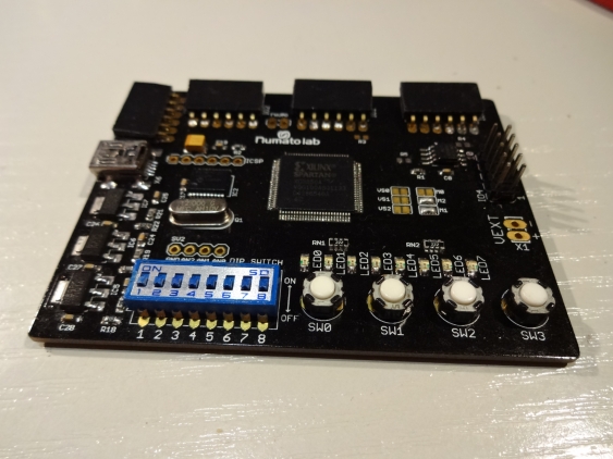
Just a quick update on the Numato FPGA boards I reviewed in the past. Right now they seem to be in the process of creating a whole eco system around them, to make it even easier to start the journey into the world of FPGAs.
While following their blog, I noticed that Numato started to add some breakout boards to their offerings, that are intended to go directly to their FPGA boards. Judging from the layout they should work directly with the Elbert beginners board. But Numato also has a new FPGA offering, the Waxwing mini module. Its just a bare bones FPGA breakout containing the bare minimum of components (FPGA, regulators, configuration memory and DRAM). There is a baseboard available which shares the same connector system as the Elbert board. so the new extension boards are working with it too.
As of now, there are the following modules available:
- Breadboard module, great for experiments
- Push button module for inputs
- LED module, they easiest way for output
- Seven segment display module with four digits
- LCD Display for showing data
- VGA display module for advanced display stuff
- SD card module
- CS4344 audio module
And there are also breakout modules for Mimas and Saturn, to connect the new boards to their large pin headers. Well done, Numato!
Right now Numato is giving away one of the VGA modules. If you miss that, just look every week at their blog for new freebies.
Wireless power contest - strategies for charging a battery pack, part 2
In the last part of my wire less power contest article I had a look at options for charging a battery pack by dividing it into single cells for charging. Since all the options proved to be too complicated for my purposes, I will take a look at how to charge the battery pack at once.
Continue readingWireless power contest - strategies for charging a battery pack, part1
When deciding for my basic plan to use a LiIon battery pack, I already knew that charging a LiIon battery pack will probably be the biggest challenge right now. So now it gets time for looking deeper into the issues of that problem.
Continue readingWireless power contest - outlining the basic plan
After I changed plans for last week, and did a second round of measurements, its now about time to write a little bit more about the actual project.
The basic idea is to augment an existing RC car by removing its battery pack, and to replace it with a Li-Ion battery. This battery then should get charged by wireless power transfer. Then its enough for my son to just take the car, put it on the charger station before going to sleep, and it should be ready the next day.
Continue readingMeasuring the performance of the wireless power demo kit - an update
When measuring the performance of the wireless power demo kit, I forgot to look at the efficiency. So I repeated my test series, but also measured the current consumption of the transmitter board.
I also ordered a cheap Qi receiver off eBay. Since my son has more than just a single toy I intended it to be used for other ones. Since it comes from China I did not expect to it get before a month or so, but shipping was really fast this time. So I found it in my mail on Thursday, and added it to the test series.
Continue readingMeasuring the performance of the wireless power demo kit
When talking about wireless charging, one of the questions that always come up is: what are the distances this will work for? I did answer this question already for another wireless charging kit, so I was curious what the Qi (or WPC) standard had ins store.
I’m interested in the maximum distance that is suitable for transferring a significant amount of power. Especially I wanted to know how well the transmit and receive coils need to be aligned with each other. After all, we are talking about a kid and its toys - one cannot expect millimeter precision when trying to charge to a toy over night.
Continue readingAXP1G57 configurable logic demo board - first impressions
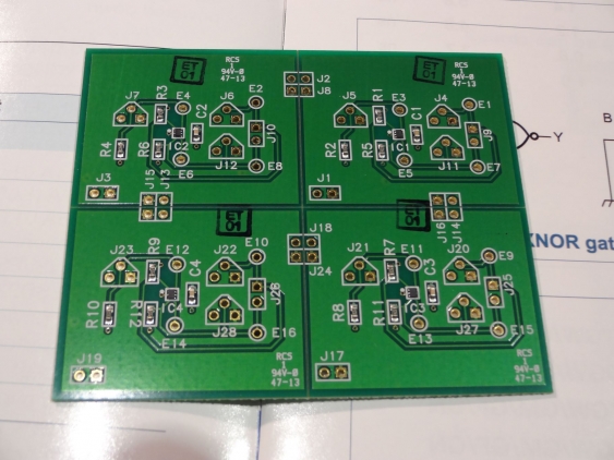
So the evaluation board from NXP has arrived safely. Its larger than I expected (about 7.5 by 6 cm) - because its four boards in one:
Each of the four parts of the board contains a single 74AXP1G57 chip (the really small blob in the middle), surrounded by connectors to all pins, and the needed passive components (and even some more).
Continue readingUnboxing the Wireless power demo kit - first impressions
So Würth was really fast with sending the Wireless power demo kit - one of the advantages of living in Germany :)
This is what I found after opening the package:
If you look closely, you see the small tweezers on the right. Indeed - more than I expected from a demo kit…
Continue readingAnother month, another contest - gimme wireless power!
Sometimes my timing is just bad. When I applied for the AXP configurable logic contest end of last year, I didn’t know that there would be another contest waiting for me. But when I stumbled on the Beyond the phone challenge by Element14, I could not resist to register for that too. It falls into my “I always wanted to do that” category…
When I started adding wireless charging to my sons night light, I already knew that this would be useful for other toys too. So this contest was the perfect excuse to start working on that. And there was even the perfect object to be modified:
Continue readingAnother year, another contest
Since already have way to many project on my waiting list, I participate less in design contests than I used to. (I didn’t even come around to describe the projects I already did for them).
So when I stumble over one, I look whether it sound interesting or not. Sometimes there are interesting prices (I still need a decent scope beside my iMSO104), sometimes the idea is just fun (like for the last one). Sometimes the contest theme hits a nerve and its something I always wanted to play with.
When NXP informed me about their new “AXP logic design contest”, I was wondering in which category I should put it. The prices where not really for geeks of electronics engineers. And Doing something useful with just four configurable logic gates?
Continue readingBuilding a PICkit3 clone
I already own a PICkit2 clone for a while, and it worked without problems. But since it has been deprecated by Microchip for several years now, it doesn’t get any updates anymore. And so I found several times that it just doesn’t properly support the PIC chip I wanted to use. One can compile the pk2cmd application on Linux, to get at least programming support (it seems to be updated from time to time). But when used from MPLabX, only limited device support is available. And there is no PIC32 support at all.
So when I saw the updated QFP protoboard from Dangerousprototypes, I thought I might have a go on building my own PK3. The schematics for it are available from Microchip (in the user guide), and the needed firmware can be found in the PICkit3 scripting tool package. So I spent my Free PCB coupon on this board, and started another project.
Continue readingUsing Xilinx iMPACT in batch mode
When using Xilinx ISE for programming CPLDs, there are two steps needed for programming:
- first implement the design (thats the process taking all the sources and translate to a SVF file)
- and then use iMPACT for program the CPLD with the SVF file
But when I started working with FPGA (with the new Numato Labs FPGA boards, I found out that there are now four steps involved until the design can be tested:
- first step is still implementing the design
- the a programming file needs to be created in ISE (thats the bit-stream file)
- then iMPACT can take the bit-stream file and creates a PROM file
- the last step is using iMPACT to transfer the PROM file into the Flash memory on the FPGA board
When checking whether a design can be translated properly, and adheres to all timing requirements, only the first step (design implementation) is needed. After that, all three steps need to be executed - every time. Thats tedious, and one even needs to have two different iMPACT projects for the last two steps (and the second one doesn’t seem to pick up changes to the PROM file, so iMPACT needs to restarted).
So it got time to automate this.
Continue readingContinuous temperature monitoring
Two years ago, when we returned from our skiing vacation, there was a nasty surprise waiting for us: with outside temperatures of down to -20° (celsius), our heating system had shut down. At one point, the pilot flame went out, and without it the heater could switch on again. I don’t know the reason for that (and it hasn’t happened since then), maybe there was a drop in gas pressure. Fortunately the temperatures were not so low for the vacation of last year, but for this year I decided I would like to be able to handle this problem.
Since I cannot really alert the service technician automatically (maybe I could, but he wouldn’t get into the house anyway), I want to know at least that there is some kind of a problem. Some I need some kind of temperature monitoring.
Continue readingA first look at the new Saturn and Mimas FPGA boards from Numato Labs
Even before the Elbert FPGA board (which I already had a chance to review)came out, Numato Labs worked on a FPGA board with a Spartan 6 on board (the Elbert board comes with a Spartan 3A). It was designed to contain an additional SDRAM module, but unfortunately the first version had some major issues. So I was rather delighted to some, nearly one year later, read the news that the board now got finished and is available. Even better, Numato Labs made two different versions: Mimas as a pure FPGA board, and Saturn as the larger one with additional SDRAM (512MBit DDR RAM).
Tom was, again, so kind to send me over one of each board. So I got a late christmas present (only by a week, and that even just because our local Fedex office closed down on the days between Christmas and New Years Eve). Thanks again!
Continue readingSome more memories
While looking at my parents attic for some old stuff of mine I not only found my old electronics experimenters kit, but also my old Lego boxes. My son already got the more generic bricks I owned as a kit (together with all the sets he got for Christmas and his birthdays already). But I also owned a whole lot of Lego Technic sets, and bought myself a Mindstorms RIS shortly after they came out. And while digging around in the attic I found the latter one…
This is the original RCX version 1.5, still complete with the yellow brick and the infrared tower (connected via serial port). I also added the accessory kit later on.
Continue readingMigrating the frequency counter to PSoC5
In the last article I ended with the question whether to move on on the PSoC4 and add some features, or to move over to the PSoC5 before doing so. Since I would need a DAC for the next stepping (adding a comparator with variable trigger level), I took a deeper look at the PSoC4 data sheet.
It comes with two DACs, but since they are current output DACs, I would need an external resistor. Since the LCD shield doesn’t leave me with a way of adding components on top of the Pioneer kit, I decided to move the project over to the PSoC5 (which has two voltage output DACs).
Continue readingOld memories, old electronics kit and a new contest
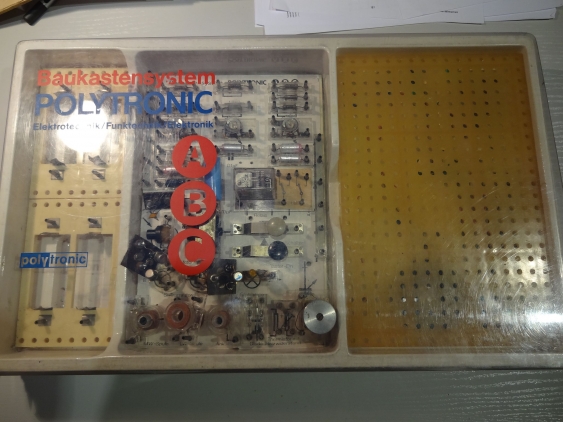
I started my career in electronics (just a private one…) when I was a kid, more than 20 years ago. Growing up in East Germany meant that possibilities and access to e.g. components or tools were rather limited. One of the most useful items for learnings was an electronics kit which I used for many experiments, and which was and important tool to gather an understanding of what’s happening in an electronic circuit.
So I was really delighted when I found, several months ago, this electronics experimenters set on my parents attic (while cleaning out some of my old stuff still stored there):
Continue readingCalibrating an old Weston 1234 digital panel meter
So after reviving the display of my panel meter, I got stuck in my search for a manual. After a while, I started looking more deeply at all references I found and got lucky. Someone looking for a model 1230 manual got referenced to a model 1242 manual, and this one looked it was useful. Although its for a somewhat different model, it at least contained a schematic, some explanations for it and especially the steps needed for calibration.
Continue readingReviving an old Weston 1234 digital panel meter
Many years ago I got my hands on an old panel meter (I think I got it from friends of my parents). It was 4.5 digit meter, with a full scale range of 20 Volts. This looked handy for using it in a power supply.
Unfortunately I found out rather soon that it wasn’t working properly. its zero point was off by a large margin, and the full scale range was reading about 2 volts less than it should. Since there was no Google back then (even no Internet access at home), it was virtually impossible to get my hands at a manual for it. And when opening it up, I found myself with 5 potentiometer for calibration…
Continue readingImproving the PSoC4 frequency counter
So in the first part we have seen that the PSoC can implement nearly anything you can draw as schematic from logic gates (or analog building blocks, though I didn’t use any). But the solution I implemented doesn’t make use from any of the PSoC-specific features. So in this part of the series, I will show what we can use and how it makes out life easier.
Continue readingStarting the PSoC frequency counter series
Time to get started with the PSoC series. In this first article, I will look the simplest frequency counter implementation - using a gated timer. I will show how a project is set up using PSoC Creator (I’m using version 2.2 here still, but you might also use the newly-released version 3.0).
This simple form of frequency meter is born by the definition of frequency: it just counts the number of pulses which can be detected in a time period of one second. So we need:
- a source for a one second pulse
- a counter (counting the pulses)
- a gate which starts, stops and resets the counter
One can implement this in pure hardware, but this will end up in a kind of “TTL grave” because you need oh so many ICs… So I will show how to transfer this kind of frequency counter in a single PSoC.
Continue readingPimping a kids night-light - finale grande
It really took a while to finish this project. Mainly this was because the object to be modified is in constant use, especially when I got some time to work on it. So when the rest of my family recently was away for a weekend, I took my chance.
To recap: the remaining task was to make use of the wireless charger module. I already figured out that it can supply enough current to charge the LiIon battery I installed in the night light. I also looked at the question whether its safe to be put into a kids bed.
Continue readingPlaying with a TCXO
When I started working on the frequency meter project using the PSoC, I thought it might be a good idea to get better accuracy than the normal crystal oscillator could deliver. After all, it should be more accurate than the usual gated timer version you can find on Google. A crystal oscillator (like the SG531-40 I have in my parts bin gives an accuracy of about 50-100 ppm - so it can be 0.01% off (so at 10 kHz it could be off by 1 Hz). On the other hand, the temperature-compensated oscillator (TCXO) I bought on ebay (a TCO-986) is specified with 0.5ppm - so its more accurate by a factor of 100. The TCXO also has a much lower drift over temperature and time, so it will stay accurate over a longer time. So the idea was to put this oscillator on a breakout board (it comes in SMD package) and then use it for the frequency meter.
Continue readingCypress PSoC introduction
I already mentioned the Cypress PSoC family of chips several times in this blog, but I never came around to explain a little more about them. But since I’m currently working on my frequency meter project which will get implemented with a PSoC5, I figured I can use this as a good example. So this posting will be start of a series. It will start with an overview - what are the Cypress PSoCs, which families are available, and what can be done with them. I choose the frequency counter already used before as an example. The first part will be an implementation as known to most people, which I will then further refine.
So, what is the PSoC?
Continue readingUpdate to the LDC1000 experiments
A few days after my article about the LDC1000 experiments I got some feedback from TI. They did let me know that
Continue readingthe chip can be used to design a general purpose metal detector. In this application, the coil design would need to change: increasing the coil size or adding a ferrite backing to the coil will increase the detection range.
Some experiments with the LDC1000 inductive sensor
Texas Instruments recently released their new LCD1000 inductive sensor. They touted it as a “game changing” announcement. And even though I don’t share that excitement, it looks like an interesting sensor (and I don’t work on stuff which relies heavily on position sensing like e.g. the automotive industries). So I ordered the evaluation kit to play a little bit.
Continue reading$9 Arduino - first impressions
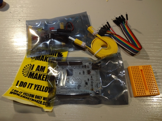
No, its not a cheap clone I scored off ebay. Maybe you have heard about the IndieGogo campaign from Borderless Electronics. I supported it rather early, because I could identify with its goals: everybody should have the chance to learn more about the technology which will drive out future. Hopefully my son will have this chance too… And when I can support such a project, and get an Arduino board by doing so, thats even better.
In the course of the campaign there were so much supporters that all stretch goals have been met (and they were four of them), and the list of what was supposed to be on board grew larger and larger. Harold from Borderless Electronics did a fantastic job on keeping the costs on the projected level (and even less). And even though the project was overfunded by about 1300%, he and his team managed to send out all the boards even before the original estimated date (for production end even) was reached (take this, pebble!).
And somehow the postal service matched this speed, and send the envelope with my board in it in only 13 days to my doorstep (the tracking page still thinks it hasn’t arrived in Germany yet :)
Upon opening, my first thought was “now that looks cool!”:
Continue readingA self-powered battery tester with an EFM32
I like to participate in electroics design contest. Its always interesting to apply skills within a given timeframe, most times also within a given frame of what to do. Many times its also a chance to get your hands on interesting hardware one would never buy otherwise. Most times I have participated so far was because the theme of the contest (or the hardware to be used) gave me the idea for an interesting project - so its most times just an excuse to build something for fun…
The same happened when Energy Micro announced, last september, their EFM32 Giant Gecko design contest. The theme was, as one would expect from Energy Micro, energy efficency. When I read about it, there came two recent events to my mind. First I had, a couple of weeks ago, disassembled a defective car temperature sensor, which left me with a single AA-cell battery holder still lying around. Second, I had many times before (and with an increasing rate) the problem to find whether some particular battery from the child toys in out household still have some energy in them or not. Until then I always I used a cheap multimeter for that which had a “battery measurement” range, but it gave only a number betwen (typically) 20 and 40, and I never knew whether that was supposed to be good or not.
So the idea hat came to my mind was: why not build a proper battery meter which can give real and accurate numbers. That can’t be so complicated! And since the EFM32 is so low-power, why not make it powered from the battery I’m currently measuring? Drawing some additional microamps from it can hardly change the results…
So I applied with this idea (and second one to, but this will be another post), and got accepted for the next round in the contest (only 40 ideas were accepted overall). So some weeks later I got a STK3700 with a EFM32GG on it my mailbox:
Continue readingBuilding a PicKit 2 clone
For most of my smaller projects using a high-performance MCU (like a Stellaris, now Tiva, STM32F or Cypress PSoC) is kind of overkill. Their power is not always needed and their requirements regarding supply voltages make the projects more complicated and expensive (they run with 3.3V only, so level conversion might be needed, and some additional LDO). And most of them are available on large (and small-pitch) packages only, making bread-boarding and the final PCBs more difficult. So for these smaller projects I mostly choose some Microchip PICs. They are cheap, come in DIP packages, have a voltage range from (for most of them) 2.7 up to 5 volts and have a great range of available peripherals (meaning you only need to take of what you really need).
But this also means there is another platform I need a programmer for. For my first experiments I used pigpgm together with the TLVP programmer. This is a small an inexpensive programmer connected to a parallel port (yes, I still take care of having one in my PC), and this combination can program nearly all PICs which can do low-voltage-programming. And it runs on Linux, too.
But since it cannot do debugging, I decided a while ago to use a tool which is supported by the Microchip tool chain (since I’m on Linux, this meant MPLabX). There is a great number of both ICD2 and PicKit2 clone projects available, so I decided to give one of them a go. I found a good project description together with a complete PCB design. Its all through-hole, and also implements the full PK2 feature set (many clones for example skip on the level-shifting stuff so they can be used with 5 volt designs only). It had nearly all components available (except for the inductor) so it didn’t cost that much to build it…
Continue readingSchmartboard PSoC board - a review
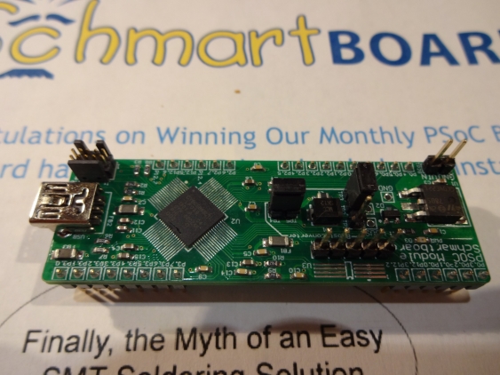
You might already know Schmartboard for their SMD breakout boards. If you do, you might also know about their line of development boards (e.g. for PICs, Parallax Propellers). And they are so nice to give away some of their boards in a monthly drawing. And it was this drawing where I got my hands on a PSoC5LP board.
So a while ago a small package arrived at my doorstep - but it spend about two weeks or so in the local customs office before it got delivered. That meant it arrived me too late to be a birthday present, But I was happy nonetheless - I like PSoCs quite a lot.
The board itself is smaller than I expected (this happens to me all the time - I always expect large bulky stuff because I forget how small all this stuff has shrunk in the last few years…). It looks quite nice - its not very dense populated. Some components are not aligned perfectly, but the soldering is without flaws.
Continue readingUSB Blaster clone
One of the tools I regularly is a JTAG adapter. For all the PIC controller I now have a PicKit2 clone, but for all the ARM MCUs you need JTAG (or sometimes SWD). Since my main operating system is Linux, it gets difficult to use the tool-chain from the processor manufacturer:
- TI provides their Code Composer Studio now also under windows, but neither the ICDI adapters nor the MSP430 Launchpad are supported there (but OpenOCD can use the ICDI and then there is also MSP430gcc)
- the LPCXpresso boards use LPC-Link, but the free IDE has a code size limit of 128k, and the LPC-Link is not supported by OpenOCD
I used for some time a Xilinx parallel cable aka DLC5, but it is quite slow. I also tried to use the ICDI on one of my TI eval kits with OpenOCD to debug the LPCXpresso, but it was quite unstable.
So when I found this Altera USB-Blaster clone using only an PIC18F14K50 I was intrigued. This sounded like what I could really use, and it should be much faster too (and not needing a parallel port is always a plus).
Continue readingHacking a garage door motor control system
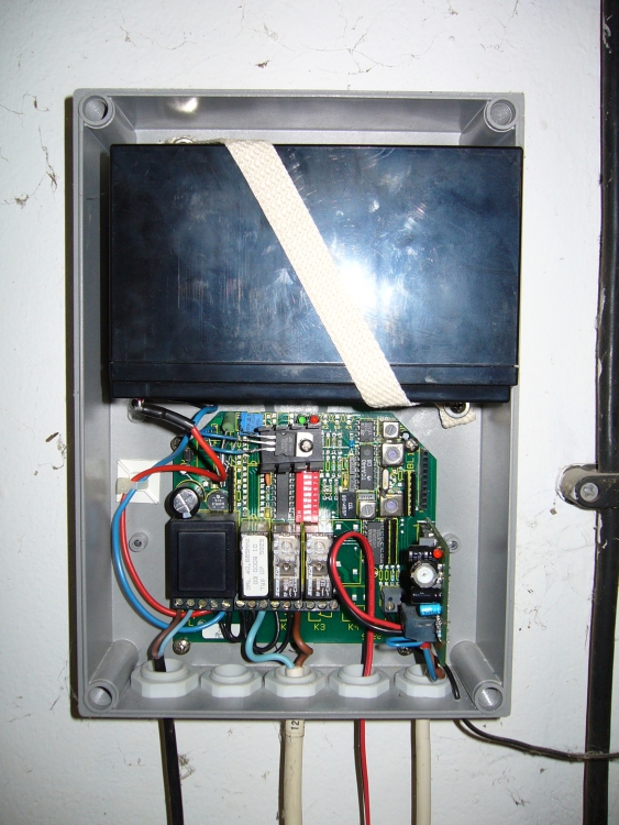
Right next to our house is a small garage for our car. The previous own installed an roller door, together with a wireless key system. To provide service also when mains power has failed, the motor control and the motor itself are powered by a lead battery which is continuously charged from mains. That has the additional advantage that no large power supply is needed (the motor runs with 12V at about 4 amps), but only a small one for charging the battery (at maybe 100 mA). But a lead battery has a finite lifetime, so it needs to be replaced at regular intervals.
About 5 years ago I needed to do this for the first time - back then I was lucky to get the car out of the garage one last time before everything stopped working. So when I noticed again that the battery was near the end of its lifespan (last fall, not so long before winter would begin), I decided to solve this problem once and forever (hopefully). Since power outages are really rare around here (I can remember of only one in the last years, and it was a planned one), there was no need to keep the battery operating. I wanted to replace it with a power supply.
Continue readingiMSO-104 scope review
This is an article I wanted to write for quite some time, but I never came around. but it just means I now have some more experience with this scope, so the review is now only based on my first impressions.
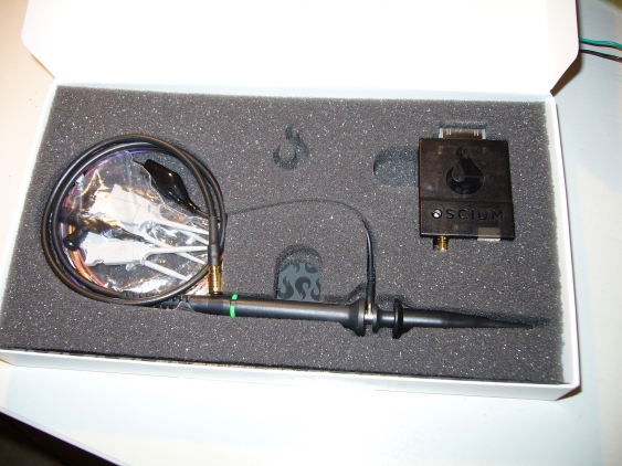
I came to my Oscium iMSO-104 scope as regular participant in the Cypress user community (which is a whole series of articles I want to write for an even longer time…). Basically it meant that as regular author their one gets rewards points, which can then be redeemed for interesting stuff. And so one day last fall a nice small package arrived at my door, containing an even smaller scope.
Continue readingLogicBoost part 2
So the LogicAnalyzer did work OK, and just needed a proper USB-to-UART converter to be used properly. What could possibly go wrong?
Enough, it turns out.
As described in the first part, I added fixed connections to one of my Launchpads to cross the Tx and Rx lines between the MSP430 and the Launchpad (to be able to use the G2553 together with the Launchpad as USB-to-UART converter). This meant I could not use the Launchpad in question when using the MCP2200 because then the Launchpad and the MCP200 would conflict. No problem, I had another one available and used that one.
Continue readingMCP2200 USB-to-UART converter
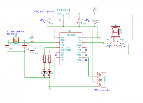
I already mentioned in the post about the LogicBoost build that I wanted to use a MCP2200 IC as the USB to UART converter. I had three of them available for quite some time but did not come around to use them. So the LogicBoost project was a good reason for that…
I used basically the reference schematic for the MCP2200, but added an voltage regulator because I the MSP430 can run only with up to 3.6V. So it gets a little bit more complicated - otherwise the MCP2200 needs only 4 external components (resonator, pull-up resistor for reset and 2 capacitors). I added also the two LEDs for transmission control, since this is always helpful for debugging.
Continue readingFirst tests with the Elbert FPGA board
A while ago Tom from Numato Labs was so kind to send me CPLD breakout board to give it a test drive. This led to a review and some interesting experiments with it. Unfortunately I had other projects ideas first, so it sat alone in its box for a while. But there will some tasks for it soon…
But a couple of weeks ago Tom asked me again whether I had use for some of the other stuff Numato has to offer. Since there was nothing I could use for a current project, he was so kind to send me a free Elbert FPGA board.
He was even so kind to send this via UPS (the CPLD board went out via normal postal service), even though that meant I needed to pay UPS fees in addition to the customs duties :( So it took less than a week for the board to arrive.
After unpacking, I found a rather small board (somehow I was expecting something big when thinking of a FPGA):
Continue readingSMT transistor test adapter
Another useful tool I built recently came from my AVR transistor tester build. I had build it with two different connector styles - one for attaching leads (via banana plugs), the other one for directly plugging in components. But this is lacking support for SMT components. I bought SMD tweezer probes (like these) on ebay recently, this covers all 2-pin components. But I had nothing to test or identify transistors.
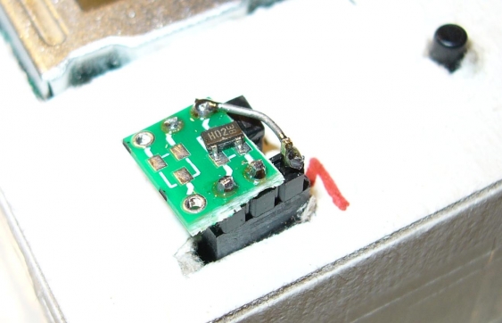
So I took a small SOT23-3 breakout board (actually it has two footprints since the other side contains a SOT23-6 breakout), soldered a 3-pin header onto it and put it into the tester. It turns out that it gets a little bit wobbly that way, and one cannot add pressure to the device-under-test to get it seated firmly. So I added the left-over half of an IC socket to the other side, to act as support. Now the board sits firmly (though not exactly horizontal) in the socket.
The wire on the right is needed because the breakout has one pin on the other side. The only drawback is that the numbering of pins on the board is in reverse to what the transistor tester uses. But I cannot put the board in the other way round because it then has no support. Maybe I will glue some foam under it one day…
TimerBlox-based test generator
I recently got some samples for the Linear Technologies LTC6990 voltage controlled oscillator. It is part of LTs series of TimerBlox components, which consists of several oscillators, a mono-flop, a delay circuit and a controllable PWM generator.
The LTC6990 comes in a SOT23-6 package and generates a square wave output ranging from 488 Hz up to 2 MHz, and is controlled by a three resistors. Two of them, forming a voltage divider, determine the center frequency and tuning range with the final frequency then determined by the third resistor. Alternatively the third resistor can be replaced by a control voltage to get a VCO.
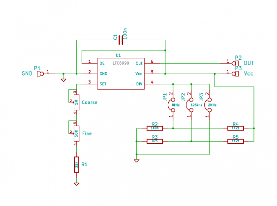
I used this chip to build a small oscillator module which can be used for breadboard experiments. I took the recommend circuit, but made the voltage divider selectable to cover the whole frequency spectrum:
The resistor values I used are not the ones proposed in the data sheet. I had the 1.21k resistors available in 1% precision, but no 1k ones. I then selected the corresponding resistors for the dividers to match the needed divider ratio. That way I can hope the ratio won’t go out of the allowed range even with aging and changing temperatures.
Instead of using a single adjustable resistors I used one for coarse and one for fine adjustment, with the smaller one 5% the value of the large one. Since there is a minimum value imposed for the set resistor, I added a fixed one too. Together they are a little bit larger then the recommend maximum value, but this just means the adjustment range got a little bit extended to the lower end (I can go as low as about 481 Hz), but it is not out the working range.
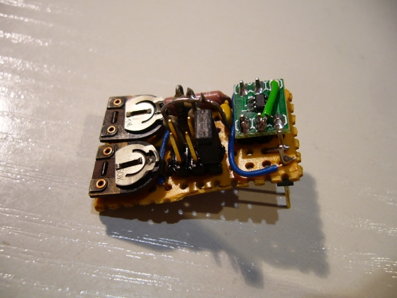
As usual, I used a small perfboard for building this. The LTC6990 went to a SOT23 breakout board on its own. For selecting the frequency range I used a 2x3 pin header and a jumper. The ranges are 488 Hz up to 15.6 KHz, 3.9 kHz up to 125 kHz and 62.5 kHz up to 2 MHz. The upper half of these ranges has less accuracy, but since it is adjusted by the user this doesn’t really matter that much.
I used longer-than-usual header pins as connector to the breadboard, so the board doesn’t touch the breadboard when plugged in. I also let some part of the pins protrude on the top so I have easy access to them.
Problem this time: setting of the frequency range did not work after building it up. It (mostly) always went to the range of 31 kHz up to 1 MHz, but sometimes also to lower ones. I checked the perfboard, the jumper, measured the voltages on the divider - everything was OK. In the end I just re-soldered pin 4 of the LTC6990, and everything was fine.
Another auto-power-off project
Since the last auto-power-off project went well, I decided to go for another problem hunting me for a while. Our satellite receivers are capable to work as PVRs when a USB disk is added. First I tried a plain USB flash stick, but its write speed was not fast enough (and with the switch to HD TV you need about 1GB per 10 minutes recording time). So I bought an external hard drive enclosure and put a 250GB drive in it.
The problem which bugged me from the beginning was that the disk stayed always on. This is not so much an issue about power consumption, but more about durability. Most disk not specifically designed for servers don’t really like to powered on always. Also, the case got noticeably warm, which also reduces the life-time of the disk.
Continue readingSome more experiments with the wireless charger
When I was discussing possible options how to mount the wireless charging module to the bed, the subject of what we call “electro smog” came up: what effects on the health might the exposure to electromagnetic radiation have?
So I started to measure what these radiation might look like. I do not own the proper equipment for that, but at least I could try to find out what kind of wave forms I could expect. To I took out my iMSO scope, and went measuring. So be warned - there are more images here than usual…
Continue readingFirst experiments with a wireless charger
So yesterday my wireless charging module from SeeedStudio arrived. Thanks again to Seeed for picking me in the give-away!
After unpacking, I found the following 2 small modules:
Continue readingPimping a kids night-light - the LiIon charger
In the first part we covered the RGB LED part of the night light. Now its time to talk about the rest of the schematic (the part on the left side).
Continue readingPimping a kids night-light
When you have kid at home, there is no absence of project ideas. When we got night light for our son two years ago, the first thing I did was replacing the batteries that came with it rechargeable ones (which is good idea for all things which are in regular use). But still it was a hassle to always recharge them - the battery compartment is secured with a screw, which will break down eventually.
So when I won a set of breakout board over at tronixstuff, I soon had an idea for one of the modules: take the RGB LED and convert the plain white night light into a colored with - with automatic cycling through all of them. And while I was working on it, I also though I could add a Li-ion battery, so I could charge it directly without opening it up all the time (there was already a connector for a power supply, but it’s kind of a bad idea to have cables in a kids bed during night).
Continue readingCD Player current savings
Recently, we bought a kid-compatible portable CD player for our son (basically it is larger and a little bit more rugged than a normal one, and has smaller buttons to be easier to use). We were just sick of hearing 6 hours “Bob the builder” during the car trips… When it arrived, we put a set of batteries in and tested it. After that, we left it until the skiing vacation. Fortunately we tested it the day before we started - the batteries were dead. So we thought “maybe we forgot to turn it off” and put a new set in. During the vacation, we mostly left it connected to its power supply. So it ran from batteries only on the car trip and during the night (when we unplugged the supply). Unfortunately, on the day we drove back the batteries were dead as before - and this time we knew it was switched off properly.
Continue readingBuilding the LogicBoost free PCB
After finishing my last free PCB build I got a new coupon from Dangerous Prototypes. Since the free PCB drawer over at DP is sometimes empty, it took a while to find something interesting. But finally a PCB for the MSP430 variant of the Logic Shrimp logic analyzer, called the LogicBoost, arrived there. It is a 6-channel logic analyzer with 20 MHz sample rate and 256k samples. So I ordered one, and it arrived yesterday. The only component I needed was a ‘573 octal latch, which I ordered in advance.
Continue readingImplementing the frequency counter part 2
So it’s finally time for the second part of my implementation. It took a while longer than intended, part because I changed more than originally intended.
Main goal was to connect to CPLD to a micro controller, to read out the counter results. The easiest way for the MCU would have been to provide a serial data stream (like SPI). But since we have 48 bits to transfer, I would need a 48 bit shift register - and there aren’t 48 registers left in the XC9572XL. So I did go an easier route and just build up a large multiplexer.
Continue readingFree PCB Build - XC95144XL Breakout Board
After finishing my last free PCB build I got a new coupon from Dangerous Prototypes. I decided to go for a xQFP prototype board this time. Unfortunately it went missing somewhere in the postal service, and there weren’t any more left. So I decided to go for a XC95144XL CPLD breakout board instead, which DP send out promptly.
Implemementing the frequency counter part 1
So this was long time since the last post. Working with a CPLD for the first time wasn’t trivial, and there are so many other things to do…
I will split this up into two parts, the first showing the frequency counter stuff itself, the second one dealing with connecting it to an MCU and showing the results.
Since I had already drawn a schematic for the simulation, which also worked fine, I decided to implement in the CPLD with a schematic also. I thought that it wasn’t too complex, and wanted to save the effort to learn VHDL or Verilog for later. It turned out to be a mixed success, mainly because the Xilinx schematics editor seems not to be intended to be used for larger projects (though it has some interesting features, it also has some quirks making stuff complicated).
Continue readingStarting with the frequency meter
The original plan for my first real CPLD project was to build a NCO (numerically controlled oscillator), which in turn should be used to build a wave generator. But shortly after I happened to find a SPG8640BN chip in my parts bin. This nice chip, which is unfortunately not produced anymore, produces a square wave output from 1 MHz down to 1/120th Hz, in 57 steps. I build a small generator with it, with 16 frequency steps between 83.3 Hz and 100 kHz. So there was no immediate need for a NCO (especially since I found a MAX038 beneath it), and I decided to build a frequency meter instead.
Continue readingJava by day...
I recently got asked how a Java programmer by day comes around to work with embedded MCUs by night. We Java developers are famous to think more in giga bytes, which is somewhat counterproductive in the embedded world.
Actually the reason is simple - I started my electronics career before I became a software developer. Back then East Germany was still alive, and electronics was an expensive hobby. So I stayed with quite small projects, more in the sense of small experiments. After the wall came down, it was easier to start real projects - but being in school limits the financial abilities a little bit. And electronics, back then,still meant only small scale stuff for someone starting in the field.
Continue readingBuilding an AVR transistor tester
I had known about the AVR transistor tester project for quite a while, but did never come around to build one. Doing a proper PCB is still a major undertaking for me…
But when Markus offered to send some his spare PCBs for free, I took my chance. I verified to have all parts available (except for the ATMega8), and the asked for one. It arrived really fast (the swiss post seems to be rather fast), but it proved Ians method of sending PCBs to be the right one:
Continue readingBuilding a Xilinx parallel cable
For my initial tests (just to check whether this board works), I just used my Buspirate as XSVF player. I flashed it with the proper firmware for that, and connected everything except Vcc to the JTAG connector. For powering the board, I connected the 5 volt line of the Buspirate with Vcc of the breakout (to avoid damaging the LDO on the board). After I discovered that I needed to set the Vio jumper, and that the BP and the drivers are somewhat picky with regard to errors (and need a complete reboot), everything worked fine.
But it is a hassle to create a XSVF file for each try, and the BP is really slow. So I went to build a better programming cable. The easiest one is called “Xilinx parallel cable II” aka “DLC5”. It gets connected to the parallel port (I fortunately still have one, even if it’s a PCI card), and contains just some driver. The schematics are provided by Xilinx for free, but I used a variation by Peter Ivanov because I just happened to have only a single 74HC125 at hand.
Continue readingInstalling Xilinx ISE under Linux
One of the tasks when starting with CPLD (or FPGA) development is to install the tool suite provided by the chip vendor. In the case of the XC9572XL this is the Xilinx ISE software. Xilinx provides a free WebPack version, which contains all the basic tools needed for the first designs.
On my initial test, I installed ISE 12.2, since I had in on a DVD somewhere. But for every start, it printed the error ‘couldn’t load XPCOM’, and some views weren’t working. So I started investigating. One of the things I wanted to make sure was that the installed version supported the Xilinx Parallel JTAG Cable III (a.k.a. DLC5), since I intended to build one. So I downloaded an older ISE version from Xilinx (10.1), and installed that one. Its release notes didn’t mention the DLC5, but the iMPACT tool (which is used for programming the CPLD) knows about it. This meant that the documentation was no reliable way to find out whether a version supports that cable or not - I needed to install them.
Continue readingBusPirate breakout free PCB build
Several weeks ago I got lucky and got a free PCB code from Dangerous Prototypes. Since I was currently working mostly with my BusPirate, and hadn’t any chips available for the other PCBs, I choose to get one of the BusPirate breakout boards. It took a while for shipment, but after Ian put into a letter, it arrived faster than expected (when looking at the address I realized than he lives nearer then expected :). I was surprised - the board was smaller than expected:
Continue readingProgramming a XC9572XL
It all started with a simple question by Tom from Numato Labs: “did you check whether the provided oscillator on the breakout works?”. So I took out my DMM and started measuring. And I got - nothing. After changing the jumper I got at least a reading for the 20 MHz setting (it showed 20.49 MHz). It turns out that my meter is only rated up to 8 MHz. So I went ahead and thought: Since I have a CPLD connected to the oscillator, why not just put some frequency divider (aka counters) on it and measure just the lower frequencies? And so did the journey begin into the land of CPLD programming…
First of all: Xilinx ISE WebPack 12.2 doesn’t really like my Kubuntu 11.10. It often complains about missing shared libraries (libxul and libxpcom). But the main features work, just some tools don’t load.
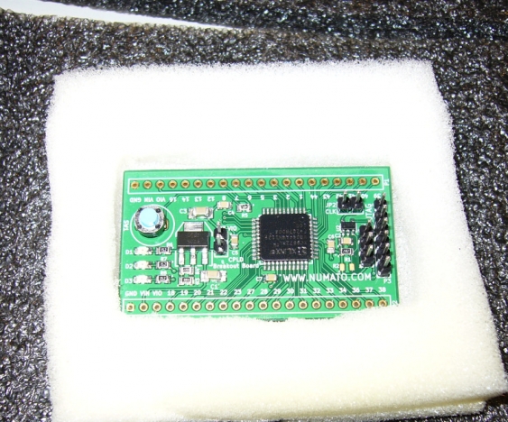
Continue readingReview - Numato CPLD breakout board
One of the things which have changed since I stopped with electronics is that much more things are now accessible to the hobbyist. 15 years ago I did know about CPLDs and FPGAs already. They cost about 50 Euros per piece, and the development software was way too expensive for a student.
So I was already interested when I saw a Dangerousprototypes post about the CPLD breakout PCB from Numato Labs . Making a PCB for SMDs is still not easy for me, and ordering one takes either a long time or some significant amount of money. When I saw that Numato offered to send me a board, I asked to get one. I figured that ordering the pieces would set me back by maybe 5 to 10 euros, which is a really cheap entry to the world of programmable logic.
But Numato Labs surprised me - they offered me to send me a fully assembled board provided I write a little bit about it - and who am I to deny that?
So 2 weeks later I found a nice little board sitting on my desk, waiting to give it a try.
Continue reading