« Small update regarding the Numato FPGA boards
| Main |Wireless power contest - strategies for charging a battery pack, part 3 »
How to design a "most useless machine" with some logic gates
So it really took me a long time to come up with the (hopefully…) final design for such a useless machine. Having some basic conditions for what parts to use for this project influenced many decisions, and made some things more complicated than originally planned. So lets have a deeper look into my solution.
First, I will explain what I used for this project, and how this shaped my decisions (and what problems arose from that). Next I will go through the whole schematic, explaining section by section my design. And last but not least I will show briefly how all of this looks in real life.
The “why”
A useless machine can be as simple as using a DPDT and a SPST switch together (the first for changing the direction, the second one for switching everything off when the motor has returned to its original position). Since I had already a geared motor available, I wanted to use it for this project. But it was a bit too fast - it would take about half a second (or even less) to hit the switch. To slow it down while still producing enough torque a PWM control circuit seemed perfect. So I reserved one of the logic gates for a RC oscillator (I tested beforehand that a duty cycle between 30 and 50 % should result in a speed that is neither too fast nor too slow).
But that meant that I also needed a H-bridge for controlling the motor - I need to control both the speed and the direction via some logic. Readily available motor control ICs all are designed for higher voltages (starting at maybe 5 V, but most are geared more for 12 V and higher voltages) - and the motor I had available is for 3 V. So the bridge would be made of discrete transistors. This also fortunate since the logic gates are specified for 2.75 V at most, so they cannot drive higher-level logic (TTL would be OK, but 5 V CMOS will get difficult already).
So I set out designing the control logic. It needed to start the motor at power-on, turn it around when hitting the switch, and then stop everything at then end (and all the time slowing it down via the PWM control). But when running the motor for the first time with the arm attached, I discovered that it would run for about half a second or so even after power had been removed. Since this would probably ruin the end-switch (the arm at the motor would travel at least 5 mm during this time), I needed a way to hard break the motor (instead of just switching off power and let it coasting).
In the end I needed one logic gate more than the four available with the eval board, which I replaced with a single transistor.
The “how”
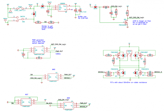
So lets have a look at the schematic:
I will walk through this in reverse order - starting with the motor and ending with the power supply stuff.
An H-Bridge
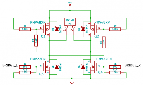
For controlling the motor, there is an H-bridge consisting of 4 FETs (2 N-FETs and 2 P-FETS):
A typical H-bridge has distinct control wires for all four transistors. Since this would mean that I need four logic gates (since each gate has only one output), I simplified the control. By using two resistors I bound the upper FETS to the corresponding other lower FET, so it gets controlled by that. This still allows full directional control, but does not allow to turn on just the upper (or lower) half of the H-bridge. How the hard braking is done gets explained later on.
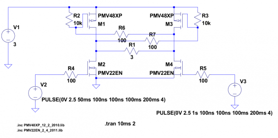
To ensure that the FETs turn on and off properly and there is enough current to the motor, I first simulated the circuit in LTSpice:
The motor is modeled as a 3-ohm resistor, and the simulation checks the current through it. Since the FETs I did use are of low resistance, and also have a low gate threshold voltage, everything is fine.
A PWM generator
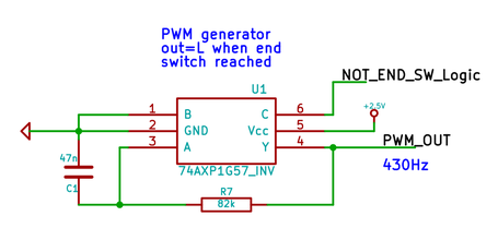
Next comes the PWM:
I configured one of the logic gates (U1) as inverter, and then wired it up as a single-gate RC oscillator. Since the gates have schmitt-trigger inputs with well-defined thresholds, this ended up in a 50% duty cycle. Originally, when testing the motor, I decided to use a PWM frequency of about 1 kHz. Later on, when testing the motor in the H-bridge configuration (and with the arm attached to it) I found out that using a lower frequency would give a much higher torque, so I reduced the frequency to about 400 Hz.
When designing the “hard stop” logic (see below), I found out that the PWM needed to output a ‘low’ signal when stopping the motor. To achieve that, I switch the logic function of the gate when reaching the end switch by pulling the C input high at that point (this is the ‘NOT_END_SW_Logic’ signal). The gate is then configured as NOR gate (since B is low), with one of its inputs (C) being high. That results in a low output.
And now for some logic
Next comes the logic controlling the H-bridge:
This is the place where the configurable logic shines:
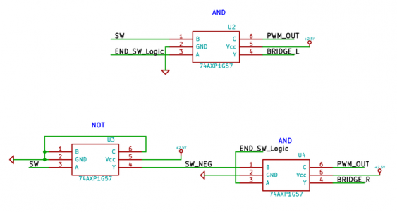
The two AND gates (U2 and U4) are configured in an identical way, each one driving one of the two sides of the H-bridge. The only difference is that they are fed complimentary versions of the ‘SW’ signal, which is the ‘public’ switch on the box. So in the end the also generate complimentary signals driving the bridge, resulting in driving the motor to different directions depending on the direction of the switch (while still following the PWM).
As long as the end position has not been reached, the ‘END_SW_Logic’ signal is high, and both gates work as AND gates. So only one side of the bridge is active, and follows the PWM signal (since the PWM pulse and the switch signal are ‘ANDed’ together), while the other side is switched off.
But when the end position is reached, the ‘END_SW_Logic’ signal will got low, and the PWM signal will do likewise (as explained above). With A being low, the gate is now configured as NAND gate with an inverted B input. With the C input driven also to low by the PWM, the output is forced to high regardless of the B input (which is the switch). That means both sides of the bridge get switched on, effectively shorting the motor - and the power supply with it. Why this is not a problem is the secret of the last part of the schematic.
But before looking at that, lets have a look at the simulation I did for that part too:
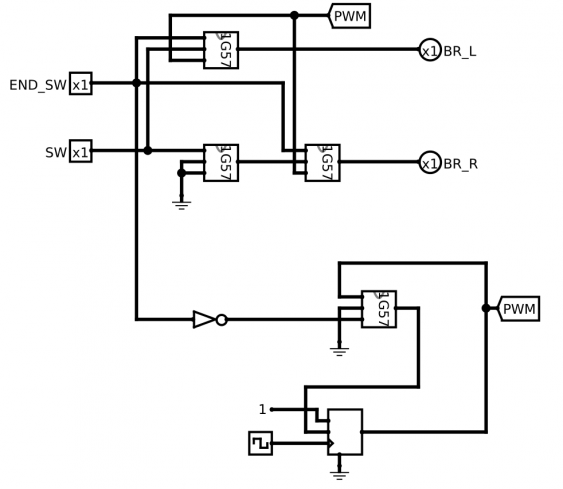
I used the Logisim tool for that. Its a great tool for simulating, testing and verifying logic circuits. I designed the 1G57 gate as a sub-circuit, and used it then in the simulation. Since Logisim only does digital logic, I replaced the RC oscillator with a single gate controlled by a D-FlipFlop (simulating the RC time constant). The signals from the switches are modeled as inputs, and the bridge is just two outputs. This allows easy testing whether the logic is correct or not - just let the simulation run and set the inputs to the state to be simulated.
Managing power and signals
The last part of the schematic is all about the power supply and the switches:
Even though it sounds simple this was the most tricky part. The switches not only control the logic gates, but also the power to the circuit, making this intertwined with the control logic. So lets see how it works.
First, the SPDT switch SW2 (this is the one on the outside of the box) switches its output between the battery voltage and ground. This output signal is then converted by R10 and R11 to a logic-level signal (the battery is 3 V, whereas the logic runs at 2.5 V, so I’m using 2 V as logic signal). But the output of SW2 also serves as power switch, turning everything on when it gets flipped over. When that happens (and the motors starts moving), SW1 (the end position switch) also gets turned on. So D1 serves a dual purpose: it avoids shorting power to ground when the arm attached to the motor finally flips SW2 back (to reverse the motor movement). And it also decouples the logic signal ‘SW’ from the battery power, so it really follows SW2.
Next there is the LDO U5, which generates the 2.5 V for the logic eval board. Its decoupled by D2 from the battery power rail to avoid discharging its output cap C2 when power gets finally turned off (we see soon why this is needed).
Last but not least there is another logic signal created by a resistor divider - ‘END_SW_Logic’. Its high as long as the motor has not reached its end position, which is as long as either SW1 or SW2 is on. So this signal is generated from the output of these two switches (labeled ‘Vcc’). Unfortunately the PWM generator needs a logic high signal to be turned off (while producing a low output signal). So Q5 inverts the logic signal.
And here comes the catch: Q5 needs to produce a logic high when the motor should stop. But at that point both SW1 and SW2 are turned off, so the battery is disconnected, and now power is available. That’s why I added a large output cap (C2) to the LDO. It stores enough energy to power the whole circuit (the logic eval board, Q5 and the gates of the H-bridge transistors) long enough to stop the motor. D2 and D7 are just needed to avoid any reverse currents, which would discharge C2 too soon.
One might wonder how the H-bridge FETs are turned on when the battery (that powers the bridge directly, without the LDO) is turned off already? Well, since the motor is still running at that moment, it turns into a generator, producing its own supply voltage. This only stops when the motor is halted, and the it doesn’t matter anymore whether the FETs are turned on or not.
There is one catch with the evaluation board, though. All input signals are equipped with pull-down resistors, which also are rather low in value (4.7k). That is fine when trigger the inputs with logic gates or other low-impedance sources. But since I want to use as less power as possible, all input signal are of high impedance (several Megaohms). So I removed all the resistors from the board, and just left the decoupling caps in place.
The looks
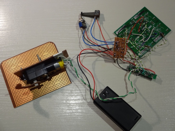
Just as a cliff-hanger, here a photo of how it looks in real life:
This is not really final, since I need to fit everything into the enclosure. So I might need to replace some wires with longer or shorter ones, especially when braking up the eval board into pieces. So stay tuned for an in-depth explanation of that, coming soon!
