« AXP configurable logic design contest wrapup
| Main |Building a multi-voltage reference for my DMMs »
wireless power - battery under-voltage lockout with multiple cells
When designing systems powered by rechargeable batteries, especially LiIon batteries, its important to ensure that the batteries are not discharged too much. For primary cells this is not a problem (except that the device won’t work anymore), but secondary cells can be permanently damaged by such a deep discharge. normally this just results in permanently reduced capacity (which is bad enough). But a LiIon battery that has been discharged too deep can actually catch fire (that happens when its charged again, since during discharge internal shorts can form inside the battery). So an under-voltage safety mechanism has to be used to ensure that never happens. Basically all single cell LiIon batteries already come with such a circuit (most times inside the case already). Many battery packs too come with it, but especially pack for RC models do not, since the high current there make that difficult. A typical cut-off voltage is about 2.5 V, sometimes as low as 2.3 V. That is a voltage where the capacity might be permanently reduced already. So I would like to have the cut-off voltage higher, at about 2.9-3.0 V. That means building my own under-voltage-lockout (or UVLO)
Such a safety mechanism gets a little bit more complicated in the case of a battery pack, since there the cut-off needs to happen when just one cell gets discharged below this voltage. So lets look how we might implement that.
Single cell UVLO
For a single cell, an under-voltage lockout is really simple. One needs a comparator, a voltage reference and a power transistor (preferably a FET). Since this circuit will always be connected to the battery, its important that it draws as less current as possible. Depending on the configuration of the comparator, one can either use a N-channel or a P-channel FET as switch. Since N-Channel FETs are more readily available, it would probably one of these. It needs to be a logic-level type, since the available gate-voltage might not be high enough for other FETs.
There are voltage references available that need only about 1 µA, and comparators with about the same operating current (or even less). But since the reference probably has a different voltage than the desired threshold, an additional resistor divider is needed - which also needs some current flowing through it. But there is an even simpler solution - by using a pre-configured comparator with integrated reference. Such circuits are used as voltage monitors, to force (or keep) MCU in reset state when their supply voltage is too low. They are available in a multitude of variations, with different voltage detection levels, and operating currents even below 500 nA. Perfect! (For a good example look at TIs TPS383x series, with the TPS3836K33 as the I would use: 220 nA supply current, 2.93 V cut-off voltage, with an active-low output, pulled to ground when voltage is too low).
Multi-cell UVLO
Unfortunately things aren’t looking so easy anymore when the battery is actually a multi-cell battery pack. Depending on the actual implementation, there are, again, multiple ways to implement this. When the pack is build from three single cells connected together, each of them can have their own circuitry (in addition to the one already build in). That means duplicating the UVLO (including the FET) three times. When one of the batteries goes below the threshold voltage, it gets switched off, and is disconnected out of the pack, turning off the power to the load.
Implementing such a solution also means that the charging circuit needs to handle a battery pack without any voltage. Since the UVLO circuit switched off the battery until an external voltage is applied, the charger cannot sense the presence and the charging state of the battery before charging starts.
So when the charger cannot handle this, such a solution cannot be used. It also won’t work when the battery pack is already pre-configured (the cells already connected together). In such a case, there can only be one FET disconnecting the load when one of the batteries goes below voltage. Thats means we still need three voltage detectors, one for each cell, but must connect their outputs together for turning the FET on and off. That, again, leaves us with another interesting problem.
We can attach the comparator, or voltage detector, directly to each cell. But then their output would be referenced to the negative pole of the respective battery. So for two of the comparators the output would not be pulled to ground actually. That means some kind of level conversion needs to take place. Opto-couplers would work, but they need too much current (try to light a LED with 1 micro;A). Logic level converters won’t work, since they need a common ground between both sides. A comparator could work, but this is what we had in the first place, so it kind of defeats the idea.
So if there is a comparator needed for level translation anyway, it can be used to do the needed comparison directly (the voltage detector cannot, since it has only a single input that is always ground referenced). So the voltage reference is set up that its referenced to ground of the respective cell, and the comparator inputs got then to the reference and positive cell output.
But when looking into actual circuits (to simulate my solution) I stumbled over a problem: All the comparators I could found that are low-power and can run with more than 12 V do not provide hysteresis. So they are not suited for slow-changing signals like a battery voltage. Having hysteresis is especially important here, because of the internal impedance of the cells. This can easily be about 100 mOhm, so when a load of 2 amp gets disconnected, the measured output voltage will rise about 200 mV. When then the UVLO has no hysteresis, it will turn on the load again. But since the voltage will the drop again, the circuit will start to oscillate.
It is possible to add hysteresis to an existing comparator by introducing feedback from the output to the input. But unfortunately the whole calculation of the needed resistors depends on the supply voltage (which will change with the batteries). And it gets even more complicated since I need a resistor divider for the battery voltage (otherwise I would need a voltage reference with about 2.9 V). So this can be done, but it looks like it will get ugly.
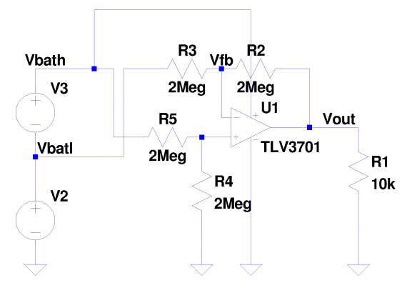
But fortunately there is a third solution: transforming the cell voltages so that they are ground-referenced. For that, we just need a difference amplifier. This is a circuit that doesn’t amplify a ground-based signal (as an OpAmp does), but the difference between two (ground-based) signals, with a ground-referenced output signal. And when the gain of such and amplifier is 1, it’s exactly what is needed. So I went to my trusted SPICE simulator again, and tested the circuit:
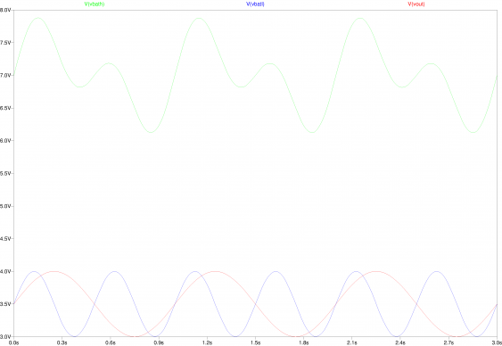
The simulation uses two voltage sources, so its like a two-cell pack. The batteries are modelled as sine-wave voltage sources, ranging from 3 to 4 V. The lower cell changes at 2 Hz, the upper at 1 Hz. So the total battery pack voltage (as measured by Vbath) varies between 6 and 8 V. When we now run the simulation, the output of the differential amplifier should give us 3 to 4 V again, changing with 1 Hz, ignoring the voltage of the lower cell (as measured by Vbatl):
Look good! The configuration of the difference amplifier as show here is the same as planned for the final circuit. The TLV3701 is a low-power OpAmp, running with up to 16 V supply while needing only 0.8µA of current. (With the TLV3702 there is also a two-channel version available) As important as the low supply current are its low offset voltage (5mV) and the really low input bias current (0.1 nA). The latter is important because the resistors defining the gain are of really high value here (to reduce current flowing through them), and any input current would increase the offset of this circuit. But 0.1 nA flowing through a 2 M resistor only results in an additional offset of 0.2 mV, which is quite good. Fortunately the gain of this circuit is only 1, otherwise it would multiply the offset voltages and then the accuracy would be too worse to be usable.
Combining the comparators
So now we have all the cell voltages nicely referenced to ground again (and added only about 3.5 µA to the total supply current), and can use our nice TPS3836K33 comparators again. But their still need to be combined to drive one single load-disconnect switch. This is the reason I did choose this exact model from the whole family: since the TPS3836 series has open-collector outputs, this is quite simple, their outputs can be connected together directly. The gate for the load-switching N-FET is pulled high with a 2 M resistor (so its active normally). When one of the comparators asserts it output, it pulls the gate down, and disconnects the load.
This solution has the additional advantage that the charger can connect directly to the battery pack, so it won’t get disconnected. In fact the whole circuit looks like a real battery to the load (and can be swapped in and out at any time). Important difference: when treated the right way, it will never be empty.
Outlook
Wuerth was so kind to send over an additional transmitter coil, so the next post will probably again be about some measurements. I will also take another look at the receiver coils, and find out how good they match into the EVM. So I will take out the frequency meter and the scope, and dive in.

