Some more experiments with the wireless charger
When I was discussing possible options how to mount the wireless charging module to the bed, the subject of what we call “electro smog” came up: what effects on the health might the exposure to electromagnetic radiation have?
So I started to measure what these radiation might look like. I do not own the proper equipment for that, but at least I could try to find out what kind of wave forms I could expect. To I took out my iMSO scope, and went measuring. So be warned - there are more images here than usual…
A look at the transmitter
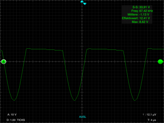
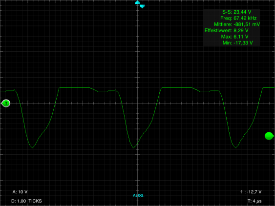
First I looked at the transmitter side, without adding any load at the receiver side:
This waveform looks rather strange - it looks like a clipped sinewave. The positive clipping happens to be at the supply voltage (which was just below 9 V for these measurements). But the signal swing much more below ground, so the p-p voltage is about 33 V (the iMSO UI is unfortunately in German, and I cannot change that…). The frequency is at rather low 67 kHz. Interestingly, when increasing the voltage to 12 V, the frequency also goes up to about 75 kHz (and then the p-p voltage increases to about 40 V). The reverse is also true - when lowering the supply voltage to 5 V the frequency goes down to about 58 kHz. So there is clearly a free-running oscillator at work here.
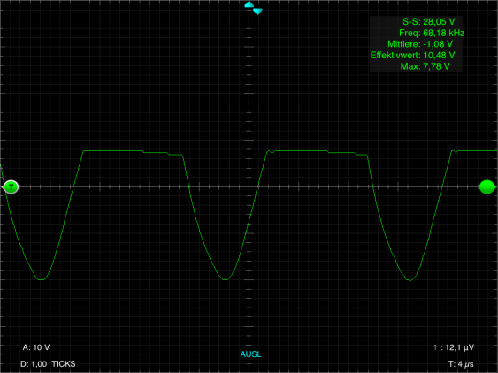
When adding a 91 ohm load to the receiver, the wave form changes only a little bit:
The frequency stays the same, but the p-p voltage sinks. Most of the change happens at the negative half of the sine wave, the positive clipping changes to so much. Note that the average voltage value stays at about -1 V, while the effective value gets reduced by about 2 V.
And a look at the receiver
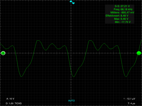
When we look at the receiver side, the wave forms look different:
One can still recognize the original clipped sine wave, but it looks much more distorted. I think this comes from the rectification and voltage stabilization process on the receiver. Whats more interesting is that the voltage I measure here is about the same as on the transmitter coil. But since the two coils look alike, this is to be expected.
Now lets transfer some energy…
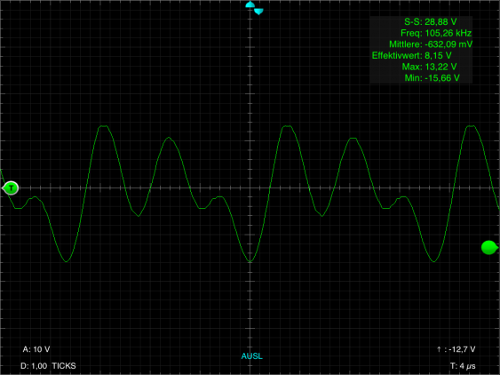
But look what happens when the two coils get shifted against each other (see the last article about why I’m concerned with that):
Since now the coils are not aligned anymore, the receiving coils is located in the electro-magnetic field in a place where the field is not uniform anymore, but somewhere else. Basically, the two coils form a transformer to transfer energy - its just that the core is missing here. And since this core is the main element for making sure that the magnetic energy gets transferred from the transmitter to the receiver, a normal transformer is much more efficient. As longs as the coils are aligned properly, the receiver coil ‘sees’ the same magnetic field as the transmitter coils creates. But then the coils are moved, different parts of the receiver coil now ‘see’ different parts of the magnetic field at different times (remember, the magnetic fields changes with about 68 kHz), we get a distorted wave form.
But the measurement last time showed that this doesn’t matter too much, as long as the overlap is large enough. So what does happen when we add the aforementioned 91 ohm to the receiver output?
It just looks more like what the transmitter actually sends, just the voltages are lower. Both effects are due to the load - the overshoots we see without look are flattened because all the current goes into the load.
Is it safe?
So how does this leave us with the original question - is it safe?
Since the frequency of the magnetic field is not so high, I don’t care about all the problems associated with mobile phones and whether they cause cancer or not. We are not talking about microwave frequencies here, so there will be no heating effect from the transmitter coil into the body (except what the coils transmit directly since it gets warm by itself).
For more thought, we can look back at the measurements from last time. We put 1W up to, at most, about 1.7 W of energy into the transmitter, to get 0.25 W of energy from the receiver (50 mA at 5 V). The maximum distance we can achieve that is about 1 cm. This means that at 1 cm the power has already dropped to 25% (or even less). And since the strength of the magnetic field drops of with the cube of the distance, for any distance about 5 cm or so it should be near zero. So as long as our son doesn’t sleep with its head on the transmitter, he should be safe. And even if he does, the energy we are talking about should not be enough to cause any harm.
But there is another lesson for me from these measurement: I really should make sure that the supply voltage doesn’t go above 12 V (even thought the module goes up to 16 V). Because when the transmitter frequency reaches 77.5 kHz, it will disturb any DCF77 clock nearby, which won’t be so nice.
