Starting the PSoC frequency counter series
Time to get started with the PSoC series. In this first article, I will look the simplest frequency counter implementation - using a gated timer. I will show how a project is set up using PSoC Creator (I’m using version 2.2 here still, but you might also use the newly-released version 3.0).
This simple form of frequency meter is born by the definition of frequency: it just counts the number of pulses which can be detected in a time period of one second. So we need:
- a source for a one second pulse
- a counter (counting the pulses)
- a gate which starts, stops and resets the counter
One can implement this in pure hardware, but this will end up in a kind of “TTL grave” because you need oh so many ICs… So I will show how to transfer this kind of frequency counter in a single PSoC.
New project creation and Creator intro
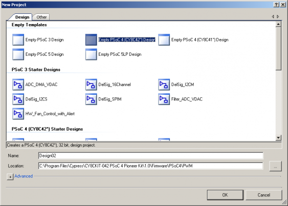
First, we starts up PSoC and create a new project. This shows up a wizard asking what kind of project we would like:
I will start with a PSoC4 (42xx series) because that is what’s used on the Cypress Pioneer Kit. But I could also choose from a series of started projects which make use of specific components and show their use. Now I just need to tell Creator where on my disk I want this project to be saved, and here we go:
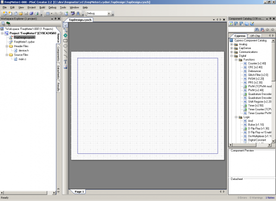
In contrast to all other IDEs for embedded development it doesn’t startup with the code editor, but with a schematic editor. On the left side the list of project files is shown (as in most other IDEs too), and on the right side the list of available components. For each component a small explanation is shown on the bottom. A right click reveals the options to look at the detailed data sheet or example projects. For now just have a look at what interesting stuff is there…
The schematic
I won’t go into the details of how top enter the schematic itself, there is plenty of documentation and training videos available from Cypress.
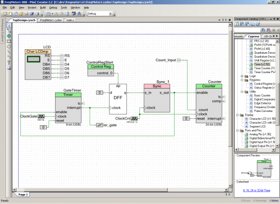
So the schematic I’m using looks like this:
It might look unfamiliar, but if you know what the symbols mean it becomes quite clear. On the the top left there is the LCD module, which tales care about connecting to the Text-LCD module used for showing the results.
Anything else is for the counter itself: on the left we start with a timer component creating a 1 Hz signal. It is driven by a 100 Hz clock (which is created by the internal clock system). The PSoC4 would be perfectly capable to deliver a 1 Hz signal from its clock system. But since it is not possible to create an interrupt driven by a clock signal directly (clocks cannot be used as data signals directly), instead a timer is used.
Its output drives the clock signal of of a D-Flip-Flop, which acts as a gate. The DFF gets reset (or rather preset, since the components in the PSoC usually work with active-high signals) by a ‘control register’. This is just the notion of how the code can send stuff to the hardware in a generic way (the other way round is called a status register). The component to the right is the counter used for counting the pulses, thats why its ‘count’ input is connected to the pin symbol ‘Count_Input’. The component in-between, called ‘Sync_1’ is needed because the counter component wants to work on signal synchronized to its input clock. But since the DFF gets preset with an asynchronous signal, the enable input of the counter needs to be synchronized. This ensures nothing strange will happen…
Component configuration
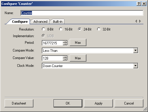
Next step is to configure the component. For example the counter needs to be set as ‘up-counter’ with 24 bit resolution. For that, one just double-clicks on their component and configures everything needed in a nice dialog:
There is no need to look for register definitions or stuff like that. The parameters configured here also influence the API which is generated for that components. For example, since the counter is 24 bits wide, the method reading the current counter value returns an uint32_t instead of a uint8_t which would be used for the 8-bit-counter.
The timer component used for generating the gate pulse gets configured in a similar way, but it will just be a 8-bit-counter with a period of 100.
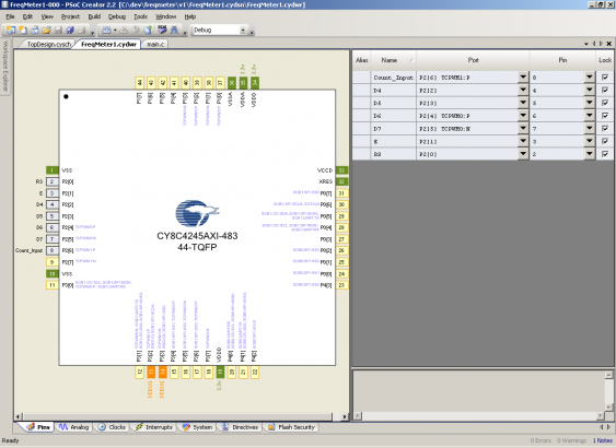
Next step is to define where the input pins goes. You might remember that on the schematic I defined the pin with a name (‘Counter_Input’), but did not specify a physical location. PSoC allows to connect basically any pin to any physical location, which is done in the so-called ‘design-wide resources’ editor:
For each pin used in the project, we can define here which physical port should be used. This allows quick reconfiguration in case one finds out that the physical mapping is not optimal or needs to be changed. There are no other changes to the code needed!
There are some restrictions, though. Some pins have more capabilities that others (higher current drive strength, or the ability to define which logic level to use). Some components also have dedicated pins assigned to them, which must be used (esp. in the PSoC4 the communications block are affected). But mostly you are free to do what you want…
Note that I also defined the Pins for the connection to the LCD module. If you want to try this project (see below) you should probably verify them…
The design wide resources also include configuring the clocking system (using an external crystal, defining the internal frequencies and stuff like that). But I leave this in its default state.
Source code
Last thing needed is the code - I’m just showing the main.c file here:
#include "device.h"
#include "tinyprintf.h" // normal stdlib won't fit in flash
on Creator 2.2

volatile uint8 triggered=0; // ISR flag

// ISR itself, just sets flag
CY_ISR_PROTO(ISR_Gate);
CY_ISR(ISR_Gate)
{
    triggered=1;
    GateTimer_ReadStatusRegister(); // and clear interrupt flag
}

void main()
{
    // start all components
    LCD_Start();
    LCD_ClearDisplay();

    ControlRegStart_Write(0);

    GateTimer_Start();
    Counter_Start();
    Counter_Enable();

    CyGlobalIntEnable; // enable interrupts

    isr_gate_StartEx(ISR_Gate);

    // start the first measurement
    ControlRegStart_Write(1);
    ControlRegStart_Write(0);

    // and the just wait for the results
    for(;;)
    {
        if (1==triggered)
        {
            // get results
            uint32 result=Counter_ReadCounter();

            // print to LCD
            char buffer[16];
            tfp_sprintf(buffer,"%lu",result);
            LCD_ClearDisplay();
            LCD_PrintString(buffer);

            // reset counter and restart everything
            Counter_WriteCounter(0);
            ControlRegStart_Write(1);
            ControlRegStart_Write(0);

            // reset ISR flag
            triggered=0;
        }
    }
}
It really is that simple. There is no complex setup needed, just the components need to be started. Each time the gate gets closed by the timer, an interrupt is triggered (this gets configured in the timer component dialog as well). The ISR assigned to this notifies the main loop of that event (by setting a flag). The main loop then reads the current counter value, writes it to the display and the restarts the measurement cycle.
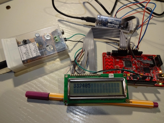
Now the code just needs to be compiled, and transferred to the PSoC. I’m using a Miniprog3 for that, but the Pioneer kit comes with its own debugger on board:
Testing
For testing I’m using my test generator, which is powered by a 1 MHz crystal and provides configurable frequencies down to 8.33 mHz (yes, thats milli). In the picture I’m measuring a 333 kHz frequency. The result is quite inaccurate, since the Pioneer kit doesn’t come with an onboard crystal. The internal oscillator of the PSoC4 is accurate to about 2%, so the 1% difference I measured is way within this range. So one of the tasks for the next articles is too use a TCXO as reference clock (I could have used it even here by using it as external clock source to the PSoC).
Last but not least, I put the project archive up for download. It is just provided for learning purposes, and must not be used for production or other serious projects…
Outlook
In the next part, I will refine this project and make use of some more advanced capabilities of the involved components. I already build a LED shield to be used with the Pioneer kit, so there won’t be any LCD module flying around on the desk…
