Pimping a kids night-light - finale grande
It really took a while to finish this project. Mainly this was because the object to be modified is in constant use, especially when I got some time to work on it. So when the rest of my family recently was away for a weekend, I took my chance.
To recap: the remaining task was to make use of the wireless charger module. I already figured out that it can supply enough current to charge the LiIon battery I installed in the night light. I also looked at the question whether its safe to be put into a kids bed.
Install the wireless receiver
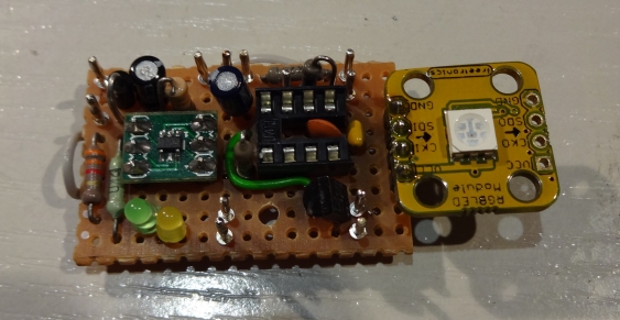
First task was to install the wireless receiver in the night light. While doing this I took the chance and moved all components to a perfboard. Until now the charger was build around a SOT23 breakout board attached to the battery, while the PIC did already sit on a board attached to the LED module.
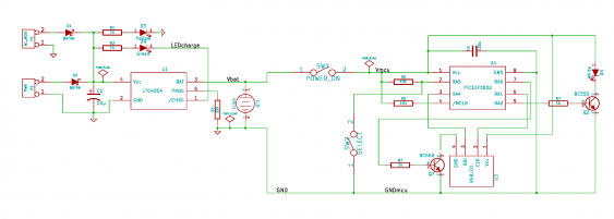
Combining everything on a single board reduces the number of wires needed to connect everything, which makes for a cleaner build. Both the wireless power receiver and the existing power socket can be used for charging the battery. So they got separated by diodes.
Redesigning the power handling
There were recently some incidents where the night light was switched completely off and then took really long to charge again. Measuring revealed that the battery has dropped down to about 2V. Since I added under-voltage detection to the PIC, this should not have happened. So I measured the current consumption in power-off mode and found a nasty surprise. When the PIC goes into under-voltage sleep, the whole circuit still consumed about 1.3 mA! Checking the data sheets revealed that the WS2801 on the RGB-LED module consumes more than 1 mA even when in idle mode.
So I added a PNP-transistor in the RGB modules ground line, to switch it off completely when not in use. Fortunately there was still one GPIO pin left on the PIC… Now the current consumption in under-voltage mode is as expected, with about 10 µA.
Mechanical work
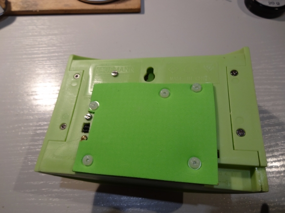
The wireless receiver coil got fixed on the outside of the night light, with the wire going through an already existing hole (no need to modify it more than necessary). The receiver PCB then is floating around on the inside, but its held in place by the thick coil wires. The coil on the outside got covered by a layer of foam rubber - I found one in nearly the same color as the enclosure. So the coil is neatly covered and should not be removed by accident:
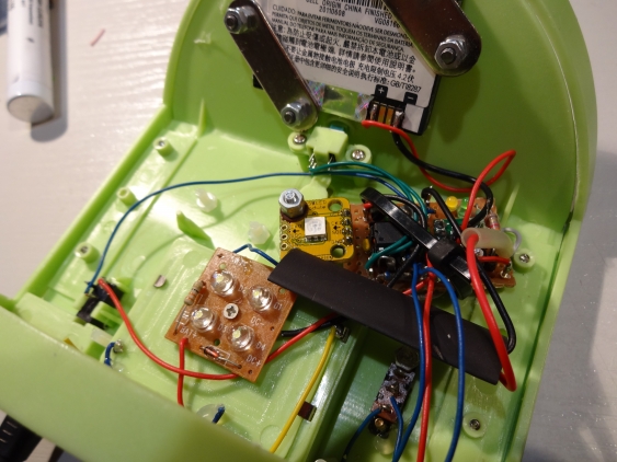
The somewhat irregular placement of the screws is because I needed free places for them inside of the enclosure - and it is quite crowded there now:
The large black heat shrink tube contains the wireless receiver PCB, so it doesn’t touch anything. I didn’t need to shrink the tube, because it fits properly even without that.
The transmitter
So the night light itself is completed, and the only missing part was to install the wireless power transmitter. First requirement was to get it somewhat kid-safe - it needs to go in our sons bed after all… Second requirement was to be as unobtrusive as possible, so it doesn’t change the nice design of our sons room.
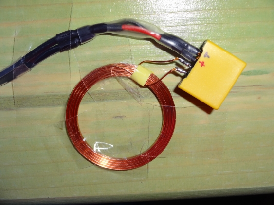
I had already decided where the transmitter should go - I needed this to know where to fit the receiver on the inside. The coil got fixed with some tape.
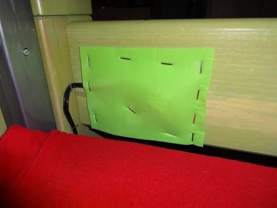
It then got covered by the same rubber foam as already used for the receiver (the bed has a similar color as the night light). I used a staple gun to fix the foam to the bed, and also to fix the wire leading from the power supply to the transmitter.
Test drive
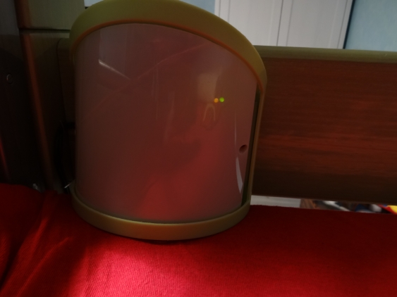
Since the light was already prepared, I just needed to put the power supply to the socket, and here we go: wireless charging, and hopefully never ever an empty battery…
The two LEDs signal that power is available (the yellow one) and the the battery is charging (the green one). They are rather dim actually, so they won’t disturb when the light itself is switched off. The charging stops when the light is moved about 1 cm from the transmitter coil, but the power LED still has another 5 mm before it goes off to.
