TimerBlox-based test generator
I recently got some samples for the Linear Technologies LTC6990 voltage controlled oscillator. It is part of LTs series of TimerBlox components, which consists of several oscillators, a mono-flop, a delay circuit and a controllable PWM generator.
The LTC6990 comes in a SOT23-6 package and generates a square wave output ranging from 488 Hz up to 2 MHz, and is controlled by a three resistors. Two of them, forming a voltage divider, determine the center frequency and tuning range with the final frequency then determined by the third resistor. Alternatively the third resistor can be replaced by a control voltage to get a VCO.
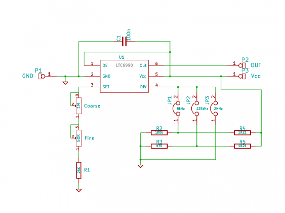
I used this chip to build a small oscillator module which can be used for breadboard experiments. I took the recommend circuit, but made the voltage divider selectable to cover the whole frequency spectrum:
The resistor values I used are not the ones proposed in the data sheet. I had the 1.21k resistors available in 1% precision, but no 1k ones. I then selected the corresponding resistors for the dividers to match the needed divider ratio. That way I can hope the ratio won’t go out of the allowed range even with aging and changing temperatures.
Instead of using a single adjustable resistors I used one for coarse and one for fine adjustment, with the smaller one 5% the value of the large one. Since there is a minimum value imposed for the set resistor, I added a fixed one too. Together they are a little bit larger then the recommend maximum value, but this just means the adjustment range got a little bit extended to the lower end (I can go as low as about 481 Hz), but it is not out the working range.
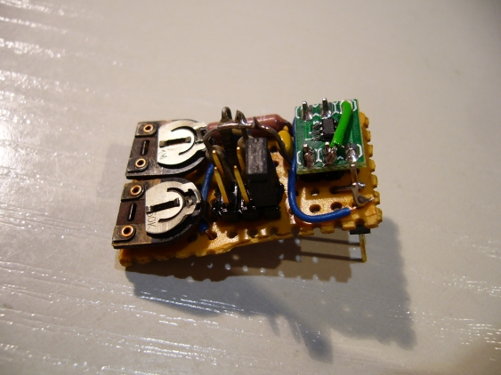
As usual, I used a small perfboard for building this. The LTC6990 went to a SOT23 breakout board on its own. For selecting the frequency range I used a 2x3 pin header and a jumper. The ranges are 488 Hz up to 15.6 KHz, 3.9 kHz up to 125 kHz and 62.5 kHz up to 2 MHz. The upper half of these ranges has less accuracy, but since it is adjusted by the user this doesn’t really matter that much.
I used longer-than-usual header pins as connector to the breadboard, so the board doesn’t touch the breadboard when plugged in. I also let some part of the pins protrude on the top so I have easy access to them.
Problem this time: setting of the frequency range did not work after building it up. It (mostly) always went to the range of 31 kHz up to 1 MHz, but sometimes also to lower ones. I checked the perfboard, the jumper, measured the voltages on the divider - everything was OK. In the end I just re-soldered pin 4 of the LTC6990, and everything was fine.

