21 items are tagged with tools:
Comparing some oscilloscopes and their probes
Since my review of the TBS1052B-EDU scope I participated in yet another Element14 contest - and part of the provided kits was yet another scope. This time it has been a TBS1202B-EDU, the larger brother of my first scope. So I thought it might be a nice exercise to compare these two scopes with each other. Since this scope comes with 200MHz passive probes (in contrast to the 50MHz probes of the TBS1052B-EDU) I will compare them too. To make it a real shootout (and to even more insight) I will include my iMSO-104 scope too, which has a meager 5MHz analog bandwidth and 12 Msps sample rate.
Continue readingSPG8640-based crystal frequency generator
One of the tools that belong in every electronics toolset is a frequency generator. There are many design out in the internet that to build your own generator. Starting with a simple 555 timer (or even just transistors), moving up to the venerable XR2206 and ICL8038 and then maybe up to the MAX038 they typically can generate since, triangle and square wave over a wide frequency range.
But they all rely on manual frequency setting, and their accuracy is in the single digit percent range (maybe as good as 0.1%). If you want to have a stable frequency source, you need a crystal based oscillator - and that typically means using a DDS chip.
When I needed a small frequency generator for a project several years ago, I did neither had the time nor the skills to build something like that. But I had in my parts box a nice chip that seemed perfect for a small tool - the SPG8640BN.
Continue readingBuilding an ATX power supply
Using ATX PSU as basis for a lab power supply is an easy way to get started when building a lab power supply. It solves all the hard parts about wiring the transformer and the voltage regulation stuff, and basically leaves only the wiring. Especially when one needs some high-current PSU, this a nice way to get a simple solution. So I had this on my ‘projects to do’ list for a while (and even started to get some components). So when I stumbled over a nice project by an italian electronics hobbyist I was intrigued. Francesco Truzzi did a great job not only on creating a nice breakout PCB, but also on adding some additional features. So when he offered to send his surplus PCBs to readers of his blog I took my chance.
Continue readingReview - Tektronix TBS1052B-EDU oscilloscope
As part of the Forget me not challenge in the Element14 community, I got an oscilloscope from Farnell to be used as part of the design challenge. Due to a communication mishap it was advertised as being the 200 MHz version, but in the end all participants got a TBS1052B-EDU. Now that I had some time to use it and get some hands-on experience with it, its about time to write a review.
Continue readingBuilding a multi-voltage reference for my DMMs
A while ago I saw in the Dangerousprototypes forums a nice project: MrRef. Its a small voltage reference, intended to verify that a digital multimeter is still within its spec. Normally one would use either a real high-precision meter (like the Agilent 3458A) or a really good, calibrated voltage reference. But these are not exactly cheap, and probably overkill for a 50$ (or cheaper) multimeter. So matseng took a not so expensive voltage reference (a MAX6350, but it onto small breakout board, together with 4 batteries, and had something which is at least more accurate than the normal hobbyists multimeter.
Seeing this I did something similar - but I used a REF5020 from TI instead:
but it was not as accurate as I would have liked (the initial accuracy is 0.1%), and the 2.048 Vv output voltage meant that its just over the range for a 2000 counts multimeter (so it read 2.05).
So when I bought a new multimeter last fall (two UT61E actually), I looked into building a new, more accurate reference, with a wider range of voltages.
Continue readingBuilding a PICkit3 clone
I already own a PICkit2 clone for a while, and it worked without problems. But since it has been deprecated by Microchip for several years now, it doesn’t get any updates anymore. And so I found several times that it just doesn’t properly support the PIC chip I wanted to use. One can compile the pk2cmd application on Linux, to get at least programming support (it seems to be updated from time to time). But when used from MPLabX, only limited device support is available. And there is no PIC32 support at all.
So when I saw the updated QFP protoboard from Dangerousprototypes, I thought I might have a go on building my own PK3. The schematics for it are available from Microchip (in the user guide), and the needed firmware can be found in the PICkit3 scripting tool package. So I spent my Free PCB coupon on this board, and started another project.
Continue readingUsing Xilinx iMPACT in batch mode
When using Xilinx ISE for programming CPLDs, there are two steps needed for programming:
- first implement the design (thats the process taking all the sources and translate to a SVF file)
- and then use iMPACT for program the CPLD with the SVF file
But when I started working with FPGA (with the new Numato Labs FPGA boards, I found out that there are now four steps involved until the design can be tested:
- first step is still implementing the design
- the a programming file needs to be created in ISE (thats the bit-stream file)
- then iMPACT can take the bit-stream file and creates a PROM file
- the last step is using iMPACT to transfer the PROM file into the Flash memory on the FPGA board
When checking whether a design can be translated properly, and adheres to all timing requirements, only the first step (design implementation) is needed. After that, all three steps need to be executed - every time. Thats tedious, and one even needs to have two different iMPACT projects for the last two steps (and the second one doesn’t seem to pick up changes to the PROM file, so iMPACT needs to restarted).
So it got time to automate this.
Continue readingCalibrating an old Weston 1234 digital panel meter
So after reviving the display of my panel meter, I got stuck in my search for a manual. After a while, I started looking more deeply at all references I found and got lucky. Someone looking for a model 1230 manual got referenced to a model 1242 manual, and this one looked it was useful. Although its for a somewhat different model, it at least contained a schematic, some explanations for it and especially the steps needed for calibration.
Continue readingReviving an old Weston 1234 digital panel meter
Many years ago I got my hands on an old panel meter (I think I got it from friends of my parents). It was 4.5 digit meter, with a full scale range of 20 Volts. This looked handy for using it in a power supply.
Unfortunately I found out rather soon that it wasn’t working properly. its zero point was off by a large margin, and the full scale range was reading about 2 volts less than it should. Since there was no Google back then (even no Internet access at home), it was virtually impossible to get my hands at a manual for it. And when opening it up, I found myself with 5 potentiometer for calibration…
Continue readingPlaying with a TCXO
When I started working on the frequency meter project using the PSoC, I thought it might be a good idea to get better accuracy than the normal crystal oscillator could deliver. After all, it should be more accurate than the usual gated timer version you can find on Google. A crystal oscillator (like the SG531-40 I have in my parts bin gives an accuracy of about 50-100 ppm - so it can be 0.01% off (so at 10 kHz it could be off by 1 Hz). On the other hand, the temperature-compensated oscillator (TCXO) I bought on ebay (a TCO-986) is specified with 0.5ppm - so its more accurate by a factor of 100. The TCXO also has a much lower drift over temperature and time, so it will stay accurate over a longer time. So the idea was to put this oscillator on a breakout board (it comes in SMD package) and then use it for the frequency meter.
Continue readingBuilding a PicKit 2 clone
For most of my smaller projects using a high-performance MCU (like a Stellaris, now Tiva, STM32F or Cypress PSoC) is kind of overkill. Their power is not always needed and their requirements regarding supply voltages make the projects more complicated and expensive (they run with 3.3V only, so level conversion might be needed, and some additional LDO). And most of them are available on large (and small-pitch) packages only, making bread-boarding and the final PCBs more difficult. So for these smaller projects I mostly choose some Microchip PICs. They are cheap, come in DIP packages, have a voltage range from (for most of them) 2.7 up to 5 volts and have a great range of available peripherals (meaning you only need to take of what you really need).
But this also means there is another platform I need a programmer for. For my first experiments I used pigpgm together with the TLVP programmer. This is a small an inexpensive programmer connected to a parallel port (yes, I still take care of having one in my PC), and this combination can program nearly all PICs which can do low-voltage-programming. And it runs on Linux, too.
But since it cannot do debugging, I decided a while ago to use a tool which is supported by the Microchip tool chain (since I’m on Linux, this meant MPLabX). There is a great number of both ICD2 and PicKit2 clone projects available, so I decided to give one of them a go. I found a good project description together with a complete PCB design. Its all through-hole, and also implements the full PK2 feature set (many clones for example skip on the level-shifting stuff so they can be used with 5 volt designs only). It had nearly all components available (except for the inductor) so it didn’t cost that much to build it…
Continue readingUSB Blaster clone
One of the tools I regularly is a JTAG adapter. For all the PIC controller I now have a PicKit2 clone, but for all the ARM MCUs you need JTAG (or sometimes SWD). Since my main operating system is Linux, it gets difficult to use the tool-chain from the processor manufacturer:
- TI provides their Code Composer Studio now also under windows, but neither the ICDI adapters nor the MSP430 Launchpad are supported there (but OpenOCD can use the ICDI and then there is also MSP430gcc)
- the LPCXpresso boards use LPC-Link, but the free IDE has a code size limit of 128k, and the LPC-Link is not supported by OpenOCD
I used for some time a Xilinx parallel cable aka DLC5, but it is quite slow. I also tried to use the ICDI on one of my TI eval kits with OpenOCD to debug the LPCXpresso, but it was quite unstable.
So when I found this Altera USB-Blaster clone using only an PIC18F14K50 I was intrigued. This sounded like what I could really use, and it should be much faster too (and not needing a parallel port is always a plus).
Continue readingiMSO-104 scope review
This is an article I wanted to write for quite some time, but I never came around. but it just means I now have some more experience with this scope, so the review is now only based on my first impressions.
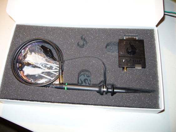
I came to my Oscium iMSO-104 scope as regular participant in the Cypress user community (which is a whole series of articles I want to write for an even longer time…). Basically it meant that as regular author their one gets rewards points, which can then be redeemed for interesting stuff. And so one day last fall a nice small package arrived at my door, containing an even smaller scope.
Continue readingLogicBoost part 2
So the LogicAnalyzer did work OK, and just needed a proper USB-to-UART converter to be used properly. What could possibly go wrong?
Enough, it turns out.
As described in the first part, I added fixed connections to one of my Launchpads to cross the Tx and Rx lines between the MSP430 and the Launchpad (to be able to use the G2553 together with the Launchpad as USB-to-UART converter). This meant I could not use the Launchpad in question when using the MCP2200 because then the Launchpad and the MCP200 would conflict. No problem, I had another one available and used that one.
Continue readingMCP2200 USB-to-UART converter
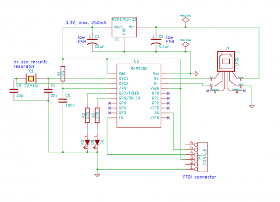
I already mentioned in the post about the LogicBoost build that I wanted to use a MCP2200 IC as the USB to UART converter. I had three of them available for quite some time but did not come around to use them. So the LogicBoost project was a good reason for that…
I used basically the reference schematic for the MCP2200, but added an voltage regulator because I the MSP430 can run only with up to 3.6V. So it gets a little bit more complicated - otherwise the MCP2200 needs only 4 external components (resonator, pull-up resistor for reset and 2 capacitors). I added also the two LEDs for transmission control, since this is always helpful for debugging.
Continue readingSMT transistor test adapter
Another useful tool I built recently came from my AVR transistor tester build. I had build it with two different connector styles - one for attaching leads (via banana plugs), the other one for directly plugging in components. But this is lacking support for SMT components. I bought SMD tweezer probes (like these) on ebay recently, this covers all 2-pin components. But I had nothing to test or identify transistors.
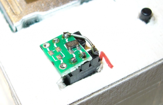
So I took a small SOT23-3 breakout board (actually it has two footprints since the other side contains a SOT23-6 breakout), soldered a 3-pin header onto it and put it into the tester. It turns out that it gets a little bit wobbly that way, and one cannot add pressure to the device-under-test to get it seated firmly. So I added the left-over half of an IC socket to the other side, to act as support. Now the board sits firmly (though not exactly horizontal) in the socket.
The wire on the right is needed because the breakout has one pin on the other side. The only drawback is that the numbering of pins on the board is in reverse to what the transistor tester uses. But I cannot put the board in the other way round because it then has no support. Maybe I will glue some foam under it one day…
TimerBlox-based test generator
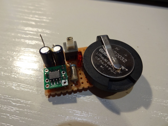
I recently got some samples for the Linear Technologies LTC6990 voltage controlled oscillator. It is part of LTs series of TimerBlox components, which consists of several oscillators, a mono-flop, a delay circuit and a controllable PWM generator.
The LTC6990 comes in a SOT23-6 package and generates a square wave output ranging from 488 Hz up to 2 MHz, and is controlled by a three resistors. Two of them, forming a voltage divider, determine the center frequency and tuning range with the final frequency then determined by the third resistor. Alternatively the third resistor can be replaced by a control voltage to get a VCO.
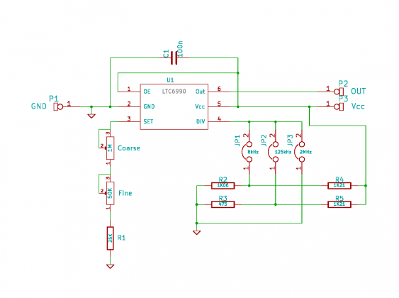
I used this chip to build a small oscillator module which can be used for breadboard experiments. I took the recommend circuit, but made the voltage divider selectable to cover the whole frequency spectrum:
The resistor values I used are not the ones proposed in the data sheet. I had the 1.21k resistors available in 1% precision, but no 1k ones. I then selected the corresponding resistors for the dividers to match the needed divider ratio. That way I can hope the ratio won’t go out of the allowed range even with aging and changing temperatures.
Instead of using a single adjustable resistors I used one for coarse and one for fine adjustment, with the smaller one 5% the value of the large one. Since there is a minimum value imposed for the set resistor, I added a fixed one too. Together they are a little bit larger then the recommend maximum value, but this just means the adjustment range got a little bit extended to the lower end (I can go as low as about 481 Hz), but it is not out the working range.
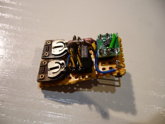
As usual, I used a small perfboard for building this. The LTC6990 went to a SOT23 breakout board on its own. For selecting the frequency range I used a 2x3 pin header and a jumper. The ranges are 488 Hz up to 15.6 KHz, 3.9 kHz up to 125 kHz and 62.5 kHz up to 2 MHz. The upper half of these ranges has less accuracy, but since it is adjusted by the user this doesn’t really matter that much.
I used longer-than-usual header pins as connector to the breadboard, so the board doesn’t touch the breadboard when plugged in. I also let some part of the pins protrude on the top so I have easy access to them.
Problem this time: setting of the frequency range did not work after building it up. It (mostly) always went to the range of 31 kHz up to 1 MHz, but sometimes also to lower ones. I checked the perfboard, the jumper, measured the voltages on the divider - everything was OK. In the end I just re-soldered pin 4 of the LTC6990, and everything was fine.
Building the LogicBoost free PCB
After finishing my last free PCB build I got a new coupon from Dangerous Prototypes. Since the free PCB drawer over at DP is sometimes empty, it took a while to find something interesting. But finally a PCB for the MSP430 variant of the Logic Shrimp logic analyzer, called the LogicBoost, arrived there. It is a 6-channel logic analyzer with 20 MHz sample rate and 256k samples. So I ordered one, and it arrived yesterday. The only component I needed was a ‘573 octal latch, which I ordered in advance.
Continue readingBuilding an AVR transistor tester
I had known about the AVR transistor tester project for quite a while, but did never come around to build one. Doing a proper PCB is still a major undertaking for me…
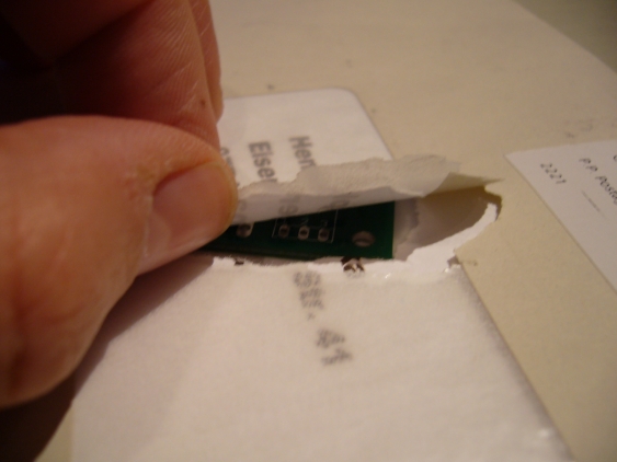
But when Markus offered to send some his spare PCBs for free, I took my chance. I verified to have all parts available (except for the ATMega8), and the asked for one. It arrived really fast (the swiss post seems to be rather fast), but it proved Ians method of sending PCBs to be the right one:
Continue readingBuilding a Xilinx parallel cable
For my initial tests (just to check whether this board works), I just used my Buspirate as XSVF player. I flashed it with the proper firmware for that, and connected everything except Vcc to the JTAG connector. For powering the board, I connected the 5 volt line of the Buspirate with Vcc of the breakout (to avoid damaging the LDO on the board). After I discovered that I needed to set the Vio jumper, and that the BP and the drivers are somewhat picky with regard to errors (and need a complete reboot), everything worked fine.
But it is a hassle to create a XSVF file for each try, and the BP is really slow. So I went to build a better programming cable. The easiest one is called “Xilinx parallel cable II” aka “DLC5”. It gets connected to the parallel port (I fortunately still have one, even if it’s a PCI card), and contains just some driver. The schematics are provided by Xilinx for free, but I used a variation by Peter Ivanov because I just happened to have only a single 74HC125 at hand.
Continue readingBusPirate breakout free PCB build
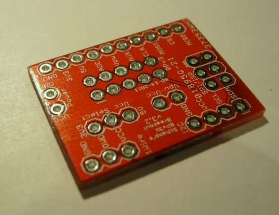
Several weeks ago I got lucky and got a free PCB code from Dangerous Prototypes. Since I was currently working mostly with my BusPirate, and hadn’t any chips available for the other PCBs, I choose to get one of the BusPirate breakout boards. It took a while for shipment, but after Ian put into a letter, it arrived faster than expected (when looking at the address I realized than he lives nearer then expected :). I was surprised - the board was smaller than expected:
Continue reading