Building a PicKit 2 clone
For most of my smaller projects using a high-performance MCU (like a Stellaris, now Tiva, STM32F or Cypress PSoC) is kind of overkill. Their power is not always needed and their requirements regarding supply voltages make the projects more complicated and expensive (they run with 3.3V only, so level conversion might be needed, and some additional LDO). And most of them are available on large (and small-pitch) packages only, making bread-boarding and the final PCBs more difficult. So for these smaller projects I mostly choose some Microchip PICs. They are cheap, come in DIP packages, have a voltage range from (for most of them) 2.7 up to 5 volts and have a great range of available peripherals (meaning you only need to take of what you really need).
But this also means there is another platform I need a programmer for. For my first experiments I used pigpgm together with the TLVP programmer. This is a small an inexpensive programmer connected to a parallel port (yes, I still take care of having one in my PC), and this combination can program nearly all PICs which can do low-voltage-programming. And it runs on Linux, too.
But since it cannot do debugging, I decided a while ago to use a tool which is supported by the Microchip tool chain (since I’m on Linux, this meant MPLabX). There is a great number of both ICD2 and PicKit2 clone projects available, so I decided to give one of them a go. I found a good project description together with a complete PCB design. Its all through-hole, and also implements the full PK2 feature set (many clones for example skip on the level-shifting stuff so they can be used with 5 volt designs only). It had nearly all components available (except for the inductor) so it didn’t cost that much to build it…
A really bad PCB
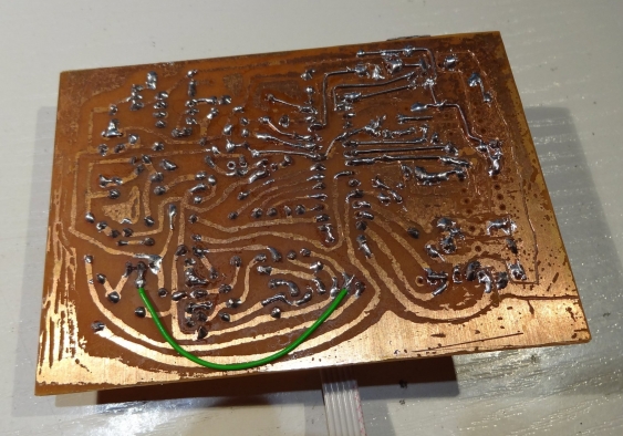
Unfortunately either my PCB board was of bad quality or my etching solution was bad. So during etching I had some parts of the board already going into over-etching (meaning small traces started to disappear) while other parts where still full of copper. So I needed to stop etching, and milled the remaining traces manually (using a Proxxon IBS/E 50 hand mill). I also needed to recreate some missing traces with small wires. So this is one of my worst PCBs ever, the copper side looks really awful.
The left side is quite OK (except for the one trace I forget and needed to patch with a wire). But the right-hand side is a mixture of over-etched traces (reworked with solid wires) and under-etched areas, where I used a hand mill to cut the traces.
Assembly
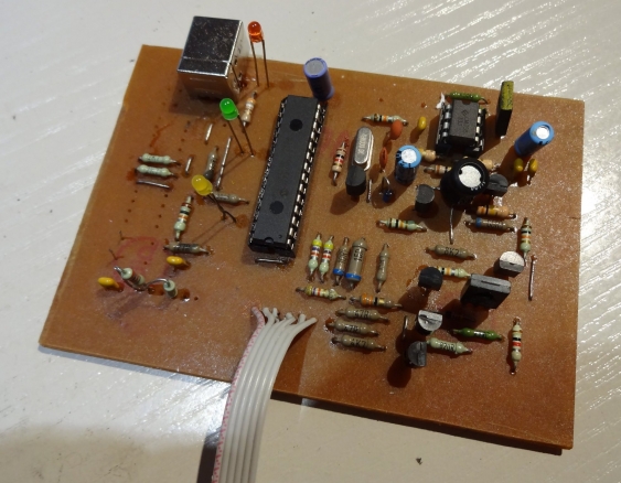
Assembling itself was quite straightforward, the PCB is layed out rather nice. After programming the PIC18F2550 (using the TLVP for the last time) I used the PicKit2 command line application to run all the self-tests. This allowed me to check whether I missed anything with my reworks (and there was some stuff, from missing wires to misplaced transistors).
I did not populate the EEPROMS, because they are used for the programming-on-the-go functionality which I don’t need.
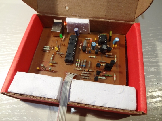
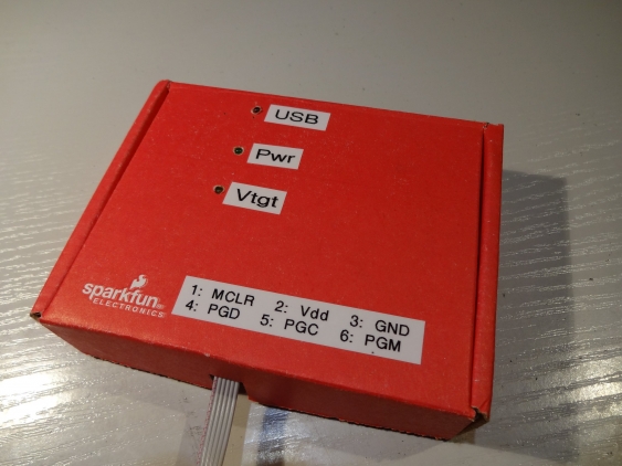
For housing I found an old Sparkfun box which did fit nearly perfect, it just needed some holes for the LEDs and connectors:
The finished PICkit2
After some test runs, and applying some reworks, I finally got it working (and after it did run with the standalone application, it worked with MPLabX on the first go). Unfortunately not all current PICs are supported when using MPLabX, so I need to resort to the standalone application sometimes. And under Linux the latest supplied binary version does support even less chips. So one needs to take the sources and compile them on Linux, and can then use the latest chip database.
So now I’m at least somewhat better off than before: for some chips I can program and debug them directly from within MPLabX. For some others, I still an external application (and can do programming only), but at least I have an USB connection instead of a parallel port (so it is also faster than before).
But since this was still not satisfying, I went of to build a PicKit3 clone too, so stay tuned :)


