« Two times is not enough - Measuring the performance of the wireless power demo kit part 3
| Main |AXP configurable logic design contest wrapup »
How to build a "most useless machine"
As promised last time, this article is about finally building the most useless machine of them all. When explaining the electronic / logic side of this project, I already talked a little bit about how it works. But now its time for some details.
The basic idea is rather simple: there a motor, connected to an arm. On the outside of the enclosure is a switch, which turns the motor on. The arm then moves the switch into its original position, and returns into the enclosure afterwards:
Video not playing? Download MP4 file instead.
The inside
But there is a little bit more involved. Since the motor needs to stop after retrcating the arm, a second switch inside the case is needed. Also, using a spring might be usefull to ensure the case really closes afterwards.
But apart from that, its a rather simple machine. I uses an old photo storage box as enclosure, and just cut its lid in half. Its was is nearly perfect for the stuff that goes into it:
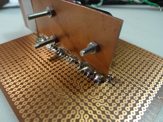
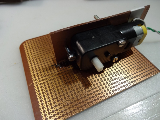
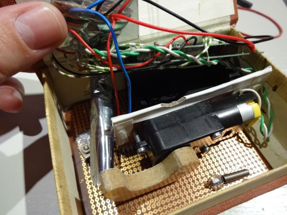
Instead of mounting everything to the box itself, I used an old experimenters PCB as base. I cut it to the size of the case, and then soldered another piece of PCB on top of it. That gave a good and strong mounting base for the motor.
The latter one came already with three mounting holes, so I just used 3 M3 screws to fix it to the vertical PCB (but not before isloating the place where the wires are connected).
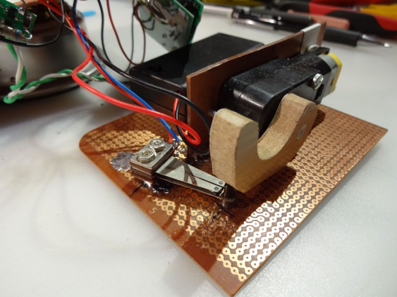
For the end-positition switch, I soldered two small M2 screws onto the bottom PCB, and mounted the switch on them (I don’t know where they actually came from, I have them laying around since twenty years or so…). The arm itself got cut out of a piece of laminate, which had the perfect thickness:
To fit the eval board to the box, I splitted it in half (it was already V-grooved, so it snaps easily). To connect power between them, I used 0.8 mm wire which also serves as spacer. At the opposing side I drilled two holes and used normal spacers (and plastic screws to avoid any shorts).
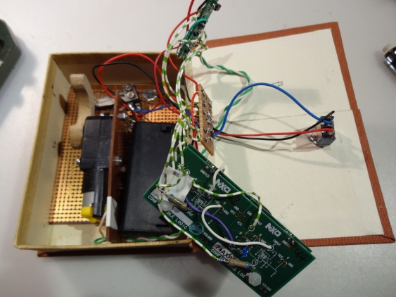
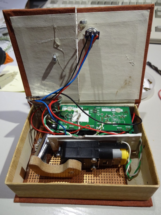
I used a SOT23 breakout board for fitting the H-Bridge stuff, the LDO and most of the passive parts (apart from the RC-oscillator stuff). For connecting everything together (the boards, the motor, the switches and the battery) I used a perfboard where all wires come together. Then I wrapped them (with an anti-static bag) for isolation, and just threw them into the case (opposite to the motor):
With some better planning beforehand, I would have had a little bit more space available. I cloud have turned around the motor so it would be on the outer edge of the case. Then there would some more space right to the arm for fitting the small PCBs in there. But even so everything fits in neatly:
Last item to add where two springs, to hold the lids of the case down. I just used hot glue to fix some nuts to the case and the lid, and hooked the springs into them. The stronger of the two got onto the side which should kept closed, and the weaker one to the part which gets opened by the moving arm.
The next (and probably last) article will be just a short summary about my experiences. And maybe I just forgot to explain some details.
