Review - Numato CPLD breakout board
One of the things which have changed since I stopped with electronics is that much more things are now accessible to the hobbyist. 15 years ago I did know about CPLDs and FPGAs already. They cost about 50 Euros per piece, and the development software was way too expensive for a student.
So I was already interested when I saw a Dangerousprototypes post about the CPLD breakout PCB from Numato Labs . Making a PCB for SMDs is still not easy for me, and ordering one takes either a long time or some significant amount of money. When I saw that Numato offered to send me a board, I asked to get one. I figured that ordering the pieces would set me back by maybe 5 to 10 euros, which is a really cheap entry to the world of programmable logic.
But Numato Labs surprised me - they offered me to send me a fully assembled board provided I write a little bit about it - and who am I to deny that?
So 2 weeks later I found a nice little board sitting on my desk, waiting to give it a try.
First impressions
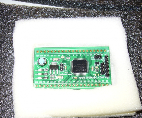
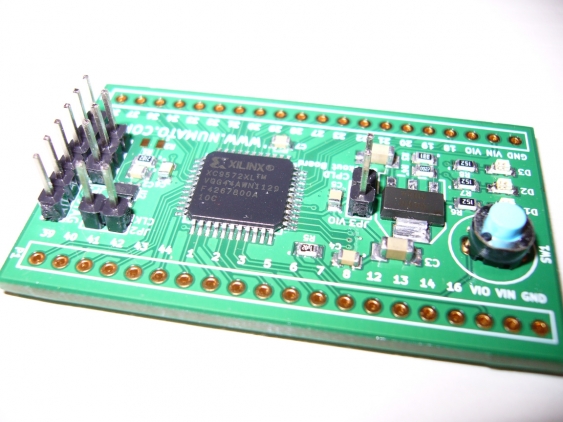
The first look and feel was nice - the board is thicker than usual making it just feel of higher quality. I also liked that all options are accessible by jumpers instead of solder bridges like the DP breakout board does. The board is populated with a XC9572XL, a LM317 regulator (which delivers up to 1 amps instead of 150 mA as on the DP board), and a LTC6905 oscillator (the small chip next to the CLK jumper).
So the next step was taking my BusPirate, and exchanging its firmware with the XSVF programming one. This step was simple - but getting the first program on the CPLD wasn’t. Under Linux I always got something like ‘no reply’, under Windows an error about unknown or unexpected XSVF commands. It turns out that one of the involved parts (the BusPirate with the XSVF firmware, the XSVF player or th FTDI driver) is somewhat picky. When something went wrong, it got out of sync and needed a complete OS reboot to work again. And since my first test after updating the BP firmware was testing the XSVF player without any board attached, it ceased working after that :(
Programming some examples
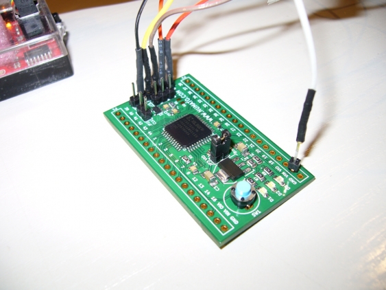
After getting that sorted out, programming the CPLD with the Dangerousprototypes examples worked fine. I didn’t use the Xilinx design software, but will explain this in a later post. For connecting the board, I used female header pins with a ribbon cable (this is the standard cable for BusPirates from Sparkfun), which worked quite nicely. Problematic here is that the JTAG header is not labeled - neither the pins itself, nor is pin 1 marked. I needed to look this up in the KiCad PCB file. (Actually it is the same as on the DP board, but one should make sure before connecting power to it…).
The power connections are not optimal
If you look closely you see that one of the wires is not connected to the JTAG header, but to the Vin pin of the board. This is because of a problem that it shares with the original design. Both boards connect the 3.3V pin of the JTAG header directly to the output pin of the on-board regulator. And both the LM317 on this board, and the SI9183 DP is using don’t like that. If you apply power to their output, reverse current will flow and might destroy the regulator (For the LM317 it is even a good design practice to add reverse diodes in parallel to the regulator in case of larger output capacitors, to protect the regulator in case of input shorts).
One might add a protection diode after the regulator, but then the voltage for the CPLD would drop below 3 volts, which might be problematic. A better solution would be to use a regulator with reverse battery protection, e.g. the LT1963A from Linear, because they are designed for such a situation (but they cost a little bit more). But for now I ended up not to use the 3.3 volts from the BusPirate, but to connect 5 volts to the regulator input of the CPLD board - I just put a header pin into the hole, without soldering it in.
Some more feedback
What else is to say about it? I quite liked the push button - it feels quite better than what is normally used. Its also nice to already have a oscillator right on the board (it even allows to choose between 20, 40 and 80 MHz), even if its not a crystal one. It might be a idea to add optional spare pads for a crystal oscillator, if one needs a higher precision.
In the beginning I got a little bit confused by the LED labels (D1..D3). Its not that all three are connected to the CPLD, only D2 and D3 are. D1 is the power LED - it would be nice to label it that way.
So the next step is to add headers for bread board usage, and to build a dedicated JTAG cable for the BusPirate before I do further experiments. I might even build a proper Xilinx Parallel Cable III (just found out that it is supported by ISE Webpack 12.2 under Linux, even if its not mentioned in the documentation). But this would be another post. My first proper CPLD project will then by to build a NCO (numerically controlled oscillator) - I still need a nice frequency generator for my lab… So stay tuned!


