Starting with the frequency meter
The original plan for my first real CPLD project was to build a NCO (numerically controlled oscillator), which in turn should be used to build a wave generator. But shortly after I happened to find a SPG8640BN chip in my parts bin. This nice chip, which is unfortunately not produced anymore, produces a square wave output from 1 MHz down to 1/120th Hz, in 57 steps. I build a small generator with it, with 16 frequency steps between 83.3 Hz and 100 kHz. So there was no immediate need for a NCO (especially since I found a MAX038 beneath it), and I decided to build a frequency meter instead.
Count different
Since this is kind of a standard project, and there are many circuits out in the wild, I decided to build it a little bit different. The typical frequency meter uses a time base of 1 second, derived from a crystal, and counts the number of input pulses during that time. This is simple to implement, and can even be done completely in a MCU. The drawback of that is that the accuracy is always 1 digit - and a frequency of 1 Hz is displayed as single ‘1’. So the lower the measured frequency, the lower the accuracy. But there is a different way, which I found in an old east-german book (“Schaltungssammlung fuer den Amateur”), which gives a constant accuracy.
Basically it works by counting both the input frequency as well as a reference frequency. The measurement stops with the first input signal edge after the reference counter has overflown. The frequency can the be calculated as fin=fref*(countin/countref). This calculation cannot be done in hardware (at least in a CPLD), it requires an MCU. The accuracy is always 1/fref, regardless of the input frequency.
So the CPLD will handle both counters (which will be 24 bit wide), and the control logic.
Using a simulator for tests
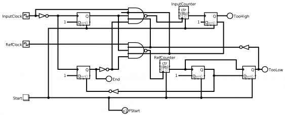
To test this, I used logisim to simulate the workings. I needed to extend the original circuit, since it used the MCU for finishing the measurement, and I wanted to that in hardware as well.
So the circuit looks like this (click on the image for a larger version):
(You can also download the logisim file.)
It work as follows:
- when the start signal is given (a 1 pulse or pressing the button in logisim), the counters and the D-flip-flops are reset
- the measurement starts with the first rising edge of the input signal, which enables, via the upper DFF, both counters
- when the reference counter overflows, the next rising edge of the input signal disables both counters, via the lower DFF
- this also sets the END signal
The reference counter at this point has the value countref-224 (because of the overflow), so this value needs to be adjusted.
The remaining flip-flops are used to detect frequencies higher than the reference frequency (then the input counter overflows), and frequencies whose period is so long it cannot be measured by 2*224 reference ticks. In both situations counting is also stopped, so especially
In logisim, play with the pulse width of the input clock to see how this detection works (the counters are only 4 bits wide in the simulation, so the measurement is quite fast).

