Implemementing the frequency counter part 1
So this was long time since the last post. Working with a CPLD for the first time wasn’t trivial, and there are so many other things to do…
I will split this up into two parts, the first showing the frequency counter stuff itself, the second one dealing with connecting it to an MCU and showing the results.
Since I had already drawn a schematic for the simulation, which also worked fine, I decided to implement in the CPLD with a schematic also. I thought that it wasn’t too complex, and wanted to save the effort to learn VHDL or Verilog for later. It turned out to be a mixed success, mainly because the Xilinx schematics editor seems not to be intended to be used for larger projects (though it has some interesting features, it also has some quirks making stuff complicated).
Using the Xilinx ISE schematic editor
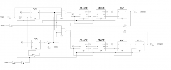
First thing to notice is that there aren’t any 24 bit counters. One can choose from a large number of different counter implementations, each with slightly different features (like loadable inputs, different version of reset and so on). But the largest counter is 16 bits - so we need to add another 8-bit-counter to it.
Apart from that the schematic looks like the one from the simulation (there are additional inverter since the D-Flip-Flops don’t have an inverted output).
One can also see the input and output connectors, together with buffers. They are needed to instruct the compiler to create external connections - otherwise the wires are only connected to other wires with the same name (possibly on other sheets).
Testing the circuit
I connected the ‘finish’ and ‘toohigh’ output lines to the LEDs on the breakout board, and the ‘start’ input to the button. My first test case involved a 20 MHz crystal oscillator connected as reference clock, and a 10 MHz one as input clock. The expected outcome was to have the ‘finish’ LED light up after about one second. But but did not - because the button on the board is connected to ground, but the original schematic expected a high pulse as start signal. After inverting this input, the LED lit up as expected.
Next test was replacing the 10 MHz oscillator with a 40 MHz one, to test the overflow mechanism. Here, only the ‘toohigh’ LEDs lights up, as wanted.
The last test used only a single oscillator as reference clock, and I created the input clock by just manually creating a single short pulse (by touching a wire to the input pin). For that, I reprogrammed the CPLD so the ‘toolow’ output is routed to one of the LEDs. This test also worked fine.
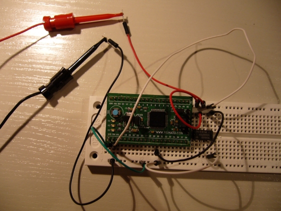
The final build looked like this:
Next step is to route the counter outputs to output pins too, and connect everything to a MCU. Stay tuned!

