« Pimping a kids night-light - the LiIon charger
| Main |Some more experiments with the wireless charger »
First experiments with a wireless charger
So yesterday my wireless charging module from SeeedStudio arrived. Thanks again to Seeed for picking me in the give-away!
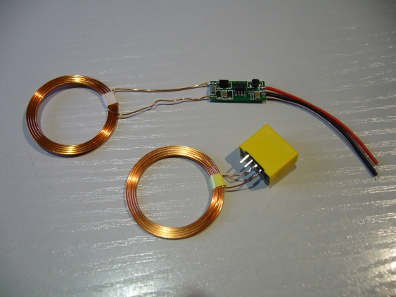
After unpacking, I found the following 2 small modules:
The transmitter is the yellow module on the bottom, the receiver is the larger PCB on the top. First thing to notice is that the transmitter has no markings, so I didn’t know which pin is positive and which one the negative supply. I needed to look on the detail page at Seeed, and then hoped that the module reflects the same PCB (which it fortunately does), so the ground connection is on the outside of the module.
Since I want to use this module as charger for my sons night light, I have some special requirements. Usually (when using this e.g. for a phone) one can be rather strict about the placement of the receiver in regards to the transmitter. But since I want to place the transmitter on the side of the bed (because its a bunk bed, the sides extend above the mattress) I cannot really enforce that the night light is placed exactly on the transmitter.
So my first experiment was to take measurements to see how far the the two coils can be shifted against each other while still delivering enough current. Originally the Li-ion charger has been set to 100 mA maximum charge current (see the last article). But when the charging can run or longer times (more or less continuously), the current can be set lower than that (but it should at least be higher than what is needed by the lamp itself). So I tested under which conditions the charging module can still deliver more than 4.2V with the desired current (the LTC4054-4.2 goes into under-voltage lock-out when the supply voltage drop below 100 mV above the battery voltage).
I measured with 4 different distances: both coils directly laying on each other, and then with 1, 4 and 8 mm between them. I then shifted the centers of both coils - the distances are measured in percent of the coils diameter. What I first noticed is that the coils are sensitive to orientation: if one is flipped over, the achievable distances are noticeable lower. Second, when the coils are shifted against each other for more than 50% (meaning one coils center is outside of the outer ring of the other coil) the voltage drops to zero immediately. The performance of the transmission drops dramatically between 40% and 50% of the diameter (between 15 mm and 19 mm). Third, the transmitter consumes about 80 to 90 mA without the receiver in range, depending on the supply voltage.
There is no big difference between 30 mA and 50 mA current. I tested with a 140 Ohm and a 91 Ohm load resistor. When requesting 50 mA, the performance is a little bit worse with larger distances between the coils. There is no big difference when the coils are directly on top of each other or 1 mm apart - the can be shifted up to 50% of the diameter against each other without large drops in voltage (with 50 mA load, the voltage drops to about 4.2V which is just usable for charging). When the coils are 8 mm apart, the usable range for shifting the coils drops to 40% (with 50 mA load the receiver delivers 4.5V).
I have added all result to a spreadsheet, which shows the complete results. For each measured combination of coil distance and difference between the coil centers, I have measured receiver voltage (for the defined load) and current consumed by the transmitter.
The picture changes somewhat though when the supply voltage is reduced from 12V down to 9V. This reduces the usable range down to 40% for close distances, and to 30% above 4 mm distance. Also, something strange happened: when I moved the coils so the didn’t overlap directly, the current consumed by the transmitter increased by up to 20 mA.
So, as an overview, here is the list of achievable distance for the various conditions:
| Supply voltage | Output current | Coil distance | Coil shift |
|---|---|---|---|
| 12 V | 50 mA | 0 mm | 15 mm |
| 12 V | 50 mA | 1 mm | 15 mm |
| 12 V | 50 mA | 4 mm | 15 mm |
| 12 V | 50 mA | 8 mm | 15 mm |
| 12 V | 30 mA | 0 mm | 19 mm |
| 12 V | 30 mA | 1 mm | 19 mm |
| 12 V | 30 mA | 4 mm | 15 mm |
| 12 V | 30 mA | 8 mm | 15 mm |
| 9 V | 30 mA | 0 mm | 15 mm |
| 9 V | 30 mA | 1 mm | 15 mm |
| 9 V | 30 mA | 4 mm | 15 mm |
| 9 V | 30 mA | 8 mm | 8 mm |
All in all this looks quite good. I’m sure I can found a kid-safe mounting for both coils which result in about 4 mm distance between them. This would allow to place the night light up to 15 mm away from the ideal position, which seems quite OK. But it seems useful to then add a power status LED to signal that the receiver is within reach of the transmitter.
