Pimping a kids night-light - the LiIon charger
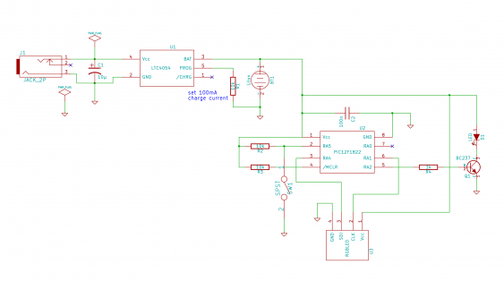
In the first part we covered the RGB LED part of the night light. Now its time to talk about the rest of the schematic (the part on the left side).
Add Li-Ion battery charging
I used the existing power connector, which is a small barrel connector, as charging power supply. It was intended to power the night light by a power supply. But since our kid has no nightstand for his bed (because its a bunk bed), we never used that option - it is a dangerous idea to have cables in a kids bed…
So I just moved the wires over from the original LED board to the charger. I did choose the LTC4054-4.2 because it can run with an input voltage of up to 10V, which allows the use of a wider range of power supplies. Most other chargers run up to 6V, so I would need to use a 5V supply, probable a USB supply. But since there was already a barrel jack connector in the night light, I wanted to use. And with the larger voltage range, there is less chance to destroy the charger by selecting the wrong voltage…
The circuit itself follows the recommend one for the LTC4054, which is rather simple. There is just a bypass cap on the input, and a single resistor setting the maximum charge current. Since the IC has an internal temperature protection, it might lower the charge current when it gets too hot.
Using the LTC4504
The LTC4054 has, when just mounted on a SOT23 breakout board, a thermal resistance of more than 150K/W. With its maximal die temperature of 120°C, this gives at most 500 mW power to dissipate. Thats why I did set it to a charge current of 100 mA - it won’t go into thermal protection mode (by lowering the charge current) even with maximum input voltage. And since the battery I’m using has a capacity of about 700 mAh, charging it doesn’t take that long.
I didn’t use the charge status output, so there is no signal when the charging has finished. But this is something which might be useful to be added later when I’m having some spare time.
What I also forgot is a reverse protection diode to protect against a wrong-polarity power supply. This might be even more urgent to add, because the one I’m using normally has configurable polarity.
Using a small PCB
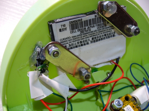
I built the charger around a SOT23 breakout, which just holds the 2 passive components which are needed. This board has then be just glued to the case of the night light. The battery itself is too heavy for that, so I used just two small metal struts to screw it to the case.
Next step would be using a wireless charging module from Seeed Studio instead of connection a power supply. That way I could ensure that the night light is always fully charged up.

