First tests with the Elbert FPGA board
A while ago Tom from Numato Labs was so kind to send me CPLD breakout board to give it a test drive. This led to a review and some interesting experiments with it. Unfortunately I had other projects ideas first, so it sat alone in its box for a while. But there will some tasks for it soon…
But a couple of weeks ago Tom asked me again whether I had use for some of the other stuff Numato has to offer. Since there was nothing I could use for a current project, he was so kind to send me a free Elbert FPGA board.
He was even so kind to send this via UPS (the CPLD board went out via normal postal service), even though that meant I needed to pay UPS fees in addition to the customs duties :( So it took less than a week for the board to arrive.
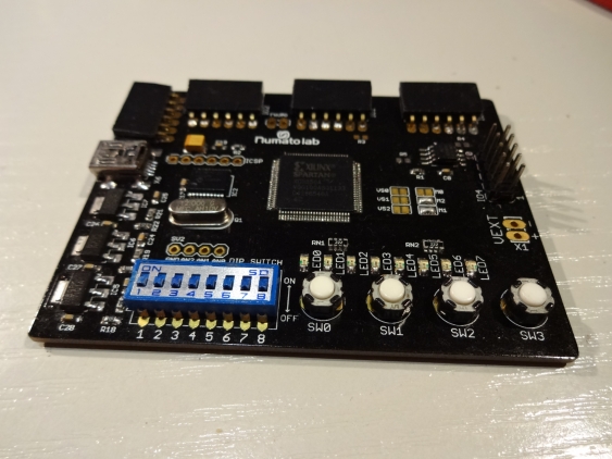
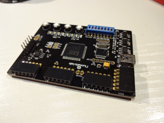
After unpacking, I found a rather small board (somehow I was expecting something big when thinking of a FPGA):
Tom was suggesting that it would be a prototype board - working but with e.g. reworks or scratches or the like. But the one I got actually looked more like a retail board - it came enclosed in a sealed plastic bag and even had a “QA passed” sticker on it…
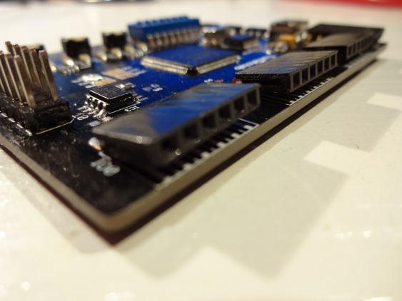
The only fault I could see were some headers which were not soldered properly flat with the board:
There were no reworks visible and the soldering looked rather fine (as the whole board does).
A first test - running a demo
When I connected the board for the first time with my computer, I was surprised to see it come alive instantly - there was a demo circuit on it showing a running light on the 8 LEDs. I find this quite neat, since it allows the user to see immediately that the board is OK.
As already said, the board is rather small, but it doesn’t need to contain that much stuff either. There is the FPGA (a Spartan 3A XC3S50A), its configuration memory and a Pic18F microcontroller handling the communication with the PCs and writing to the configuration memory. Apart from that there are just the voltage regulators, and some headers giving access to the IO signals of the FPGA.
IO is a scarce resource
Unfortunately this also means that the number of pins is limited: there are 4 headers containing 4 IO signals each (together with Vcc and ground), and another header for another 8 IO signals. This gives access to only 24 signals, which is not that much for a FPGA in VQ100 package. It would have been nice to have at least solder pads (or an unpopulated header) giving access to the rest of the IO pins. The upcoming Spartan LX9 board looks much better in that respect.
After unpacking, I followed the demo from the Numato website, and tried to program my first FPGA.
Tool usage - on Linux?
Since I’m on Linux, and re-installed recently (moving over to a full 64-bit installation), this first meant installing Xilinx ISE Webpack (again…). It turns out that one needs at least version 10.1 - older versions know about the Spartan 3A, but not in the particular VQ100 package. Fortunately I didn’t need to any of the more advanced stuff of hacking library paths like the last time. I don’t know whether its because of the version, or because of the newer Kubuntu version. But who cares :)
Following the tutorial was easy, it really goes into all the details and explains how the FPGA works, and how it is programmed. But the Elbert board doesn’t use a standard programmer supported by the Xilinx tool chain and needs its own programming for uploading the file to it. And this is a Windows-only program…
But fortunately it runs under Wine (I tested it with Crossover though). One just need to create a symbolic link. (It must be in ~/.wine/dosdevices and point from e.g. “com1” to the device in question, e.g. /dev/ttyACM0). After that, run the configuration down-loader in wine, select the serial port you just linked and the binary file created in Xilinx ISE, and there you go. Instant blinkenlights!
Some more feedback
One thing which confused me when looking at the schematics is the lack of a dedicated oscillator. There was one on the CPLD board, but here I could not see how to get a clock signal into the FPGA. It turns out that I didn’t read the website (or the UCF constrains file) properly - the clock is taken from the Pic18F MCU. That means its crystal-stabilized, and more accurate than the LTC6905 on the XC9572XL board.
I’m also missing a proper jumper for selecting the power source. There is a connector for an external power source, but to use it one need to change a solder jumper on the board. That way one cannot do this easily, but likely only once after a project has been finished and the board is ready to go be put into its final place.
All in all, I like this board. One can see it has been designed with the electronics beginner in mind. I’m not sure how good that is - I think someone starting with electronics won’t directly go to program an FPGA. But on the other hand are 50 bucks not so much money for a first good start into this fascinating world…
My next test for this board will be creating a digital filter. I want to take the output of a AMC1203 delta-sigma-modulator and create a proper output from it. This means taking a 10MHz bit-stream, and run a digital filter (a Sinc3-filter) on it. Originally I wanted to have the result on a 7-segment display, but the lack of output signals means I will probably use a HD44780 display instead (yes, this can be driven in pure hardware…).
Thanks again to Tom and Numato Labs for sending over this board, and for supporting developers out there!


