MCP2200 USB-to-UART converter
I already mentioned in the post about the LogicBoost build that I wanted to use a MCP2200 IC as the USB to UART converter. I had three of them available for quite some time but did not come around to use them. So the LogicBoost project was a good reason for that…
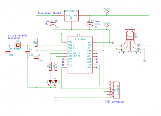
I used basically the reference schematic for the MCP2200, but added an voltage regulator because I the MSP430 can run only with up to 3.6V. So it gets a little bit more complicated - otherwise the MCP2200 needs only 4 external components (resonator, pull-up resistor for reset and 2 capacitors). I added also the two LEDs for transmission control, since this is always helpful for debugging.
As voltage regulator I used the MCP1702, which I got to like as an LDO because it can be used with all types of capacitors (not only ceramics).
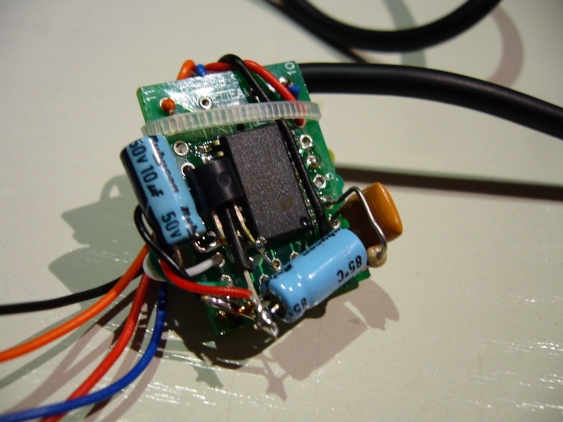
But even with the additional components I decided to fit anything on a SOIC breakout board. A 20-pin SOIC breakout provides enough space for all I needed. The regulator and its capacitors went to the top of the board. As mentioned in the schematic, I used a resonator instead of a crystal.
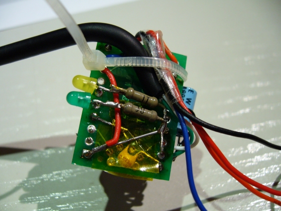
The LEDs with their resistors did go to the bottom. I did also not add an USB connector, but used a spare USB cable without one of its connectors. The converter was designated to be in the box with the LogicBoost anyway, and a fixed cable is no problem them. And I have too many of them laying around anyways…
So there is not much more to say about it. The converter worked right from the start (except that I did mixed the pins for both LEDs and needed to turn them around…). How it got added to the LogicBoost is another story…


