Hacking a garage door motor control system
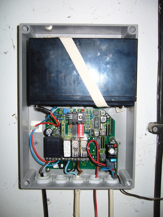
Right next to our house is a small garage for our car. The previous own installed an roller door, together with a wireless key system. To provide service also when mains power has failed, the motor control and the motor itself are powered by a lead battery which is continuously charged from mains. That has the additional advantage that no large power supply is needed (the motor runs with 12V at about 4 amps), but only a small one for charging the battery (at maybe 100 mA). But a lead battery has a finite lifetime, so it needs to be replaced at regular intervals.
About 5 years ago I needed to do this for the first time - back then I was lucky to get the car out of the garage one last time before everything stopped working. So when I noticed again that the battery was near the end of its lifespan (last fall, not so long before winter would begin), I decided to solve this problem once and forever (hopefully). Since power outages are really rare around here (I can remember of only one in the last years, and it was a planned one), there was no need to keep the battery operating. I wanted to replace it with a power supply.
Looking for a battery replacement
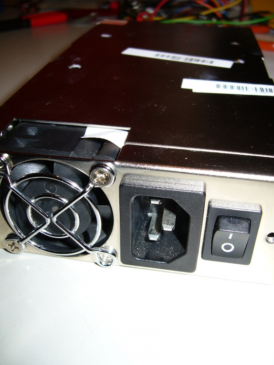
The basic idea was to remove the battery and add a power supply capable of powering the motor instead. Then I could remove the wiring from the charging circuit, and connect the supply to the motor control circuit only (which consists mainly of several relays). So the main problem was to find a beefy enough supply which was small enough to be fitted instead of the battery into the case. In the end I found an old power supply salvaged from a blade server.
It is able to deliver about 8 amps on the 12V line, which is more than enough for the motor (which takes about 10 amps when starting and 4 when running, even when pulling the door upwards). Using a computer supply also has the advantage that it doesn’t need to run continuously - one can start it easily when power is needed. Fortunately the motor control had a relay exactly doing that - going on when the motor needs to start..
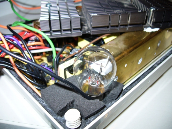
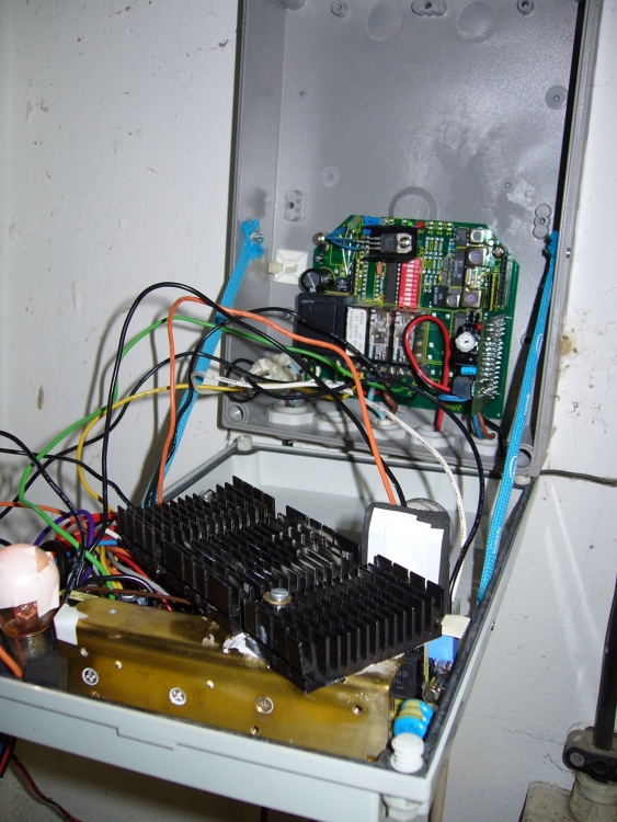
But since the supply was somewhat old, it needed a load on its 5V line to properly regulate the 12V line (newer ones are better in that regard). Otherwise the 12V voltage would drop drastically even on a small load. Some experiments showed that I would need to pull about 2 amps on the 5V rail to get at least a constant 11.5V voltage. Since I had no power resistors in the proper range available (it would have been a 6 ohms resistor with at least 15 watts), I resorted to a hack: I just used 2 12V light bulbs intended for a car instead. When powered by 5V then don’t get as hot as they normally would, and draw enough power. So I soldered wires on two of them (in parallel) and connected them to the 5V rail. The I constructed a provisional light bulb holder out of some foam and glued them in place on the side of the case.
Power supply mounting
Having solved that problem, I needed to make sure the power supply won’t overheat. It came already with a small fan (which sounded more like a turbine), but the case for the motor control is a closed one, so there would be no air exchange. And since a garage is not exactly as clean as a data center, I didn’t want to change that. So I needed to increase the thermal mass of the heat sinking, and to get at least some airflow inside of the case.
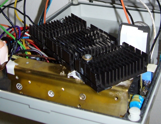
Therefore I added another heat sink on top of the opened power supply frame (which I needed to do anyway since the top frame was to wide to fit into the case anyway, because the mounting frame got in the way). For that the heat sink of an old Pentium-III came in handy, since it was rather flat and came already with a proper fan.
Everything left then was to fit everything into the case, and to wire it up. I modified the lid of the case to connect the power supply with some screws. That way I could assemble everything without disturbing existing operation of the motor control. I can now also easily remove it again when needed.
I fitted the bottom of the case with some heat resistant paper (together with aluminum foil) so that the heat of the light bulbs would be no problem should the supply need to run longer than usual. Nobody wants melted plastic on the wall…
Wiring everything up was easy because everything (including mains power) was connected via screw terminals. So I just replaces the wires from the original battery to the motor control with the wires from the power supply. I left the charger circuit untouched, now it just has nothing to charge anymore.
Experiences so far
So I have this running for more than half a year now, and I’m satisfied with it. There are no delays in opening anymore due the battery getting weak. I also haven’t noticed any heat related problems, the case doesn’t get hot (I can feel the place with the power supply under it getting a little bit warmer, but nothing to be afraid).
The only problem which has occurred so far is that sometimes the relays seems to hang. One of the remote controls needed a new battery recently, which manifested itself in needing to press is multiple times to get the door to react. And when the motor control needed to switch on and off (and reverse motor direction) several times in rapid order, sometimes the relay contacts kept stuck together until the power was switched off completely. I could also see the sparks in the relays when they are switching off, so this seems not to be good. I experimented with adding a free-wheeling diode across the relays (to remove the reverse voltage spikes when the motor gets turned off) and with adding snubber circuits, but nothing really worked.
Right now the temporary solution to that problem is two-fold: first, since I’m using already an additional external wireless receiver (to have more than one remote control for the door) which uses a 5 second timer to simulate a button press, I’m using this one only right now. The internal receiver doesn’t use any timer so when the received pulse is too short it can create the problem I encountered (it turns the motor on for a short time, but not long enough for the motor control to really react, meaning it gets turned off again). Using the external receiver only ensures that the motor stays on when it gets turned on.
Second, I configured the motor control circuit so that it switched off power just a short time after the door has finished moving. Originally, power stayed on for much longer since the rolling door has itself an end-position-switch turning off the motor when it has fully opened or closed. This change means that in a typical use-case (open the door drive into the garage and closing it again) the relays responsible for direction control only switch when no power is applied to the motor.
Outlook
This seems to help for now, but I’m still wonder whether this might be a long-term problem. So one of the projects on my list is now to replace this whole control system. I will keep the existing wireless receiver (no need to touch RF stuff, especially since it also does some sort of encryption / authentication of keys). But the relays will be replaced by an H-bridge out of 4 MOSFETS, which can withstand up to 100 amps (and 1000 amps for really short spikes). Since I then also should have some more space in the enclosure, I can also replace the power supply. For that I will use a 12V / 50W transformer, which just gets some rectification and basic smoothing. I think that reduces the risk of overloading it (the motor needs more than 4 amps when starting up). I also can control much better when power is applied and when switching happens. So I can power off the motor cleanly before reversing its direction (or switching it off by disabling all FETs), and can avoid some of the voltage spikes that way.
