USB Blaster clone
One of the tools I regularly is a JTAG adapter. For all the PIC controller I now have a PicKit2 clone, but for all the ARM MCUs you need JTAG (or sometimes SWD). Since my main operating system is Linux, it gets difficult to use the tool-chain from the processor manufacturer:
- TI provides their Code Composer Studio now also under windows, but neither the ICDI adapters nor the MSP430 Launchpad are supported there (but OpenOCD can use the ICDI and then there is also MSP430gcc)
- the LPCXpresso boards use LPC-Link, but the free IDE has a code size limit of 128k, and the LPC-Link is not supported by OpenOCD
I used for some time a Xilinx parallel cable aka DLC5, but it is quite slow. I also tried to use the ICDI on one of my TI eval kits with OpenOCD to debug the LPCXpresso, but it was quite unstable.
So when I found this Altera USB-Blaster clone using only an PIC18F14K50 I was intrigued. This sounded like what I could really use, and it should be much faster too (and not needing a parallel port is always a plus).
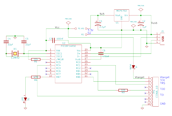
The only thing I didn’t like about it was that the 3.3V support was quite a hack. It used resistor voltage dividers on the output to act as level converter, and relied on the proper threshold levels for the inputs. So I just added a 3.3V voltage regulator (a MCP1702 as usual) to make sure the PIC18F operates at the proper frequency. In case I need to use it with a device working on 5V, I used a jumper block to be able to select the supply voltage for it.
When compared to the original schematic, I removed all the resistor dividers. For the TDI and TCK lines, I selected only one output pin - the original here uses two outputs in parallel to drive these lines. The only remaining resistor is the one one the TDO line to protect it in case of over-voltage. I also removed all the connections needed only for the Altera chips (nCE, nCS, ASDO) and connected only the four JTAG lines (TDI, TDO, TCK, TMS). If you want to get full compatibility with the USB blaster, the resistor for ASDO input line can be added again (the nCE and nCS lines can be connected directly to the PIC). Don’t forget to select 3.3V then, the Altera chips won’t stand the 5V.
As usual, I used a small perfboard to build this up (after programming the PIC18F). For the USB connection is cut a USB cable and soldered it directly to the board. Except for forgetting to put a jumper on the voltage selection it worked right from the beginning. So now I’m ready for more adventures in the ARM MCU world…
Update - Firmware
For the 18F14K50-based USB blaster firmware version 0.7 is needed. You can download it from the original page, or use my local copy. Program it onto the PIC using a PicKit3 (or a clone) - I did this using a breadboard.
