« Improving the PSoC4 frequency counter
| Main |Calibrating an old Weston 1234 digital panel meter »
Reviving an old Weston 1234 digital panel meter
Many years ago I got my hands on an old panel meter (I think I got it from friends of my parents). It was 4.5 digit meter, with a full scale range of 20 Volts. This looked handy for using it in a power supply.
Unfortunately I found out rather soon that it wasn’t working properly. its zero point was off by a large margin, and the full scale range was reading about 2 volts less than it should. Since there was no Google back then (even no Internet access at home), it was virtually impossible to get my hands at a manual for it. And when opening it up, I found myself with 5 potentiometer for calibration…
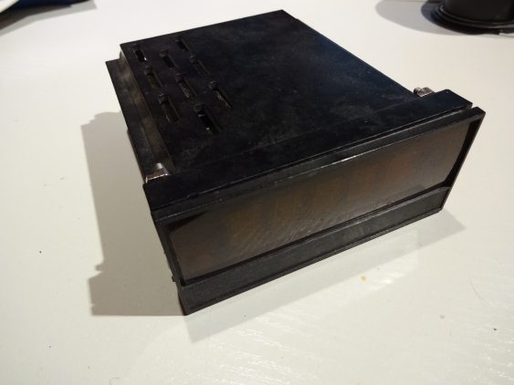
The meter was mounted in a 19 inch rack, and looks quite compact:
So back then, I tried to find out what these potentiometers are used for. For that, I noted what got displayed for various voltages (positive and negative, small and large ones and shortening the inputs). Then I modified them one by one, in different directions, and noted the changes to the displayed values for each voltage. From that I was able to somehow figure out a meaning for all trimmers. But even with that, I was not able to properly calibrate the zero point. If I did it for the negative range, it was off on the positive range, and vice versa.
So the meter got shelved, and I forgot about it. But recently I stumbled on it again, and decided to have another go on it. So I dusted it off, soldered a new mains cable on it (its 220 V powered), and turned it on again.
A old display going bad
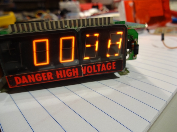
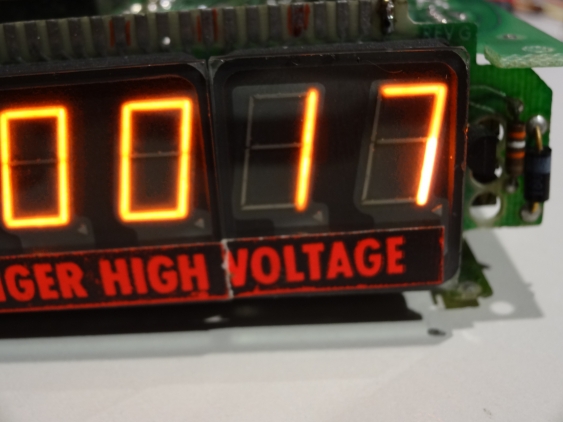
The first thing I noticed (apart from the calibration still being way off) was that the right two digits of the display are not showing full segments:
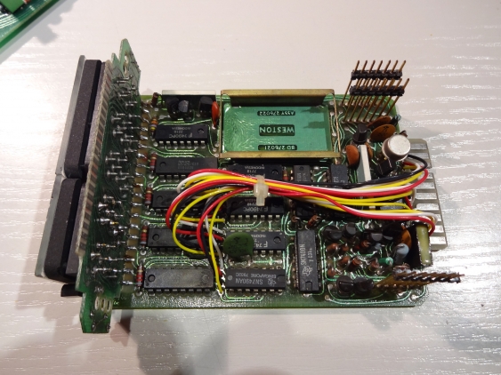
Strange thing. I could not remember having that effect when I played around many years ago, so maybe the display is now too old and defect? Or is there something wrong with the meter itself? When looking at the PCB:
there is one driver per digit (these are DS8880 constant current drivers). This would mean that exactly the two drivers for this display are defect, which is unlikely. Also since the left display is OK I can rule out problems with the power supply, or something like that.
But what display is it?
Asking Google for similar problems with VFDs yielded no results. There were also no part numbers visible, and I didn’t want to de-solder the displays. So I went to Electrical Engineering StackExchange and asked my question there. I didn’t get a solution for this problem, but an important piece of information: the display in question is not a VFD, but a gas discharge display, e.g. like a Nixie tube. Given that information, I was able to find the most likely part numbers: SP-351 for the left one, and SP-752 for the right display, both from Beckmann. These style of display is called “Panaplex”.
And the page with these parts also held the answer to my problem: Cathode poisoning. This term describes the effect that small metal particles from the lit up segments separates, and settles down on unused segments. There it can form a resistor, meaning the segment cannot light up completely anymore.
A remedy for a dark nixie tube
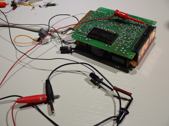
The remedy is to drive the affected segments with a current about two to ten times higher than what they are specified for. To get the right current, use either a variable current source (which would need to be able to source 100 V or more), or just use a variable resistor (but then make sure while handling it - there can be high voltages!). Start with the rated current, and increase it slowly. When the dark parts of the segment are completely lit up (even when darker than the rest), the current is right. Since I didn’t want to de-solder the display, I connected a resistor in parallel to the display driver (from the segment to ground of the driver). Fortunately, all segment pins are available as edge connectors on the display board:
I found the driver ground pin on one of the board-to-board connectors, and the other connection was made with a small grabber to the edge connector. I started with a 20k resistor and measured the current. The display is rated, according to the data sheet, for 400 to 500 µA per segment and the display driver was configured to deliver about 450 µA. The 20k resistor yielded in about 100 µA additional current, so I replaced it with a 4.7k one, and got about 400 µA. I left it at that, since the dark segments started to light up (and I didn’t feel so comfortable with driving the segments above their rated current). After waiting a while, the dark area parts started to get smaller, and interestingly the segment current started to go up. After about two to three hours for each segment, the segments are evenly lit now:
(This image is still with the additional resistor, but one can see the other segments already being fine)
So having this problem solved, I went ahead and looked at calibration. With the Internet and the invention of Google since my last try on that, I hoped for bigger luck this time. The marking on the back of the meter read “Schlumberger Model 1234”. Unfortunately, searching for that yielded virtually no result. Searching for the model number itself is not much better - “1234” is a far too common number. But when looking for the patent number printed on the back (U.S. Patent 3051939) I found a reference to a “Weston Model 1234” meter. And when googling for “Weston model 1234”, there are some manuals on ebay for that meter - but I don’t want to spend 30 Euros or so on one… So I’m on the right track, but somewhat blocked right now.
So we will see what the future holds for that meter…
