« Starting the PSoC frequency counter series
| Main |Reviving an old Weston 1234 digital panel meter »
Improving the PSoC4 frequency counter
So in the first part we have seen that the PSoC can implement nearly anything you can draw as schematic from logic gates (or analog building blocks, though I didn’t use any). But the solution I implemented doesn’t make use from any of the PSoC-specific features. So in this part of the series, I will show what we can use and how it makes out life easier.
Use counter in capture mode
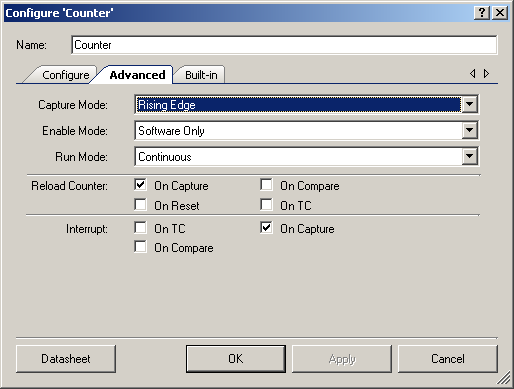
First element to remove is that control register used to create a start pulse to run a measurement cycle. To do that, we need a way to either start such a cycle another way, or the measurement needs to run continuously. Fortunately, the PSoC counters have a nice feature called “capture mode”. In that mode, the counter stores the current count value in a FIFO (up to 4 values deep), and optionally resets the counter. So we can let this counter run forever, capture (and reset) once per second and then just create an interrupt to display the results:
Since we need a 24-bit counter, we will use the UDB implementation of the counter (the fixed function block only goes to 16 bits).
Change clock generation
To free up the UDB used for the timer last time, we replace it with a PWM block, which is available as native component inside of the PSoC4. There is also a timer available as fixed function block. But we could not use it because only the UDB implementation can be enabled by a digital signal (the FF component can be started only by software)
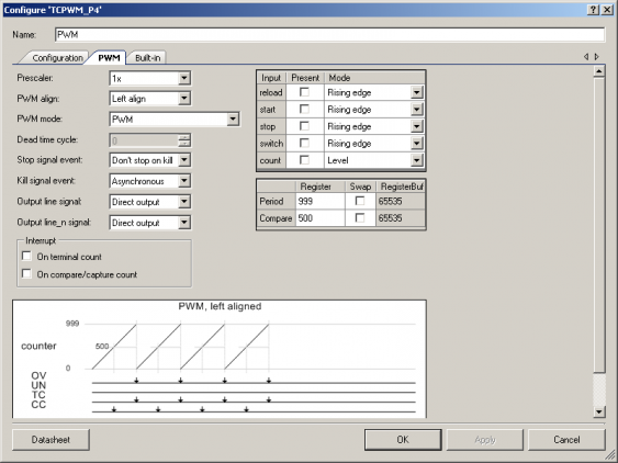
So for demonstration purposes we use a PWM component to generate a 1 Hz signal. (I could use a timer, but where is the fun in that?) So this time we feed a 1 kHz signal into it, and configure a period of 999 (actually this is highest value the counter will reach, so the period is 1 cycle longer and gives exactly the 1 Hz we need). Using a higher clock frequency this time reduces the amount of clock dividers needed
The PSoC4 has several 16-bit clock dividers, which can be chained to get the desired frequency. Using a 100 Hz clock as last time needs two of these dividers chained together, whereas the 1 kHz clock only needs one. It is not so important in this example - we don’t need that many different clocks. But in larger designs this saving can be important.
In the PWM configuration screen, we get a nice image showing which signal will trigger when. So we have a period of 999, and a compare value of 500. So we see that the compare event (which will change the output line) happens at exactly the half of the period, giving a signal with 50% duty cycle.
Apart from that configuration anything else is deactivated in the configuration, since we don’t need the special features.
Complete schematic
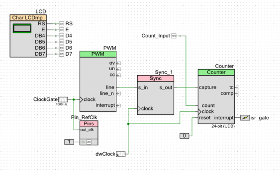
So in the final schematic, we don’t need the trigger pulse, so this register is gone. Since the counter runs continuously now, the DFF used for stopping it is also not needed anymore.
But we still need to synchronize the PWM and the counter, since they rely on different clocks. Without the synchronization, race conditions might occur.
The interrupt is driven by the counter this time, and gets triggered after each capture event.
Last element is an additional output pin. It got added so I can measure the reference frequency the PSoC uses internally (using my DMM which goes up to 4 MHz). That way I can see whether the results are accurate or not.
Software
The code gets even simpler than last time:
#include "device.h"
#include "tinyprintf.h" // normal stdlib won't fit in flash

volatile uint8 triggered=0; // ISR flag

// ISR itself, just sets flag
CY_ISR_PROTO(ISR_Gate);
CY_ISR(ISR_Gate)
{
    triggered=1;
    Counter_ReadStatusRegister(); // and clear interrupt flag
}

void main()
{
    // start all components
    LCD_Start();
    LCD_ClearDisplay();

    PWM_Start();
    Counter_Start();
    Counter_Enable();

    CyGlobalIntEnable; // enable interrupts

    isr_gate_StartEx(ISR_Gate);


    // and the just wait for the results
    for(;;)
    {
        if (1==triggered)
        {
            // get results
            uint32 result=Counter_ReadCapture();

            // reset ISR flag
            triggered=0;

            // print to LCD
            char buffer[16];
            tfp_sprintf(buffer,"%lu",result);
            LCD_ClearDisplay();
            LCD_PrintString(buffer);

        }
    }
}
We start with initializing and starting the hardware. But then we don’t need to handle the control register. The code just waits for an interrupt to occur, and the reads the latest capture value from the counter.
Results and outlook
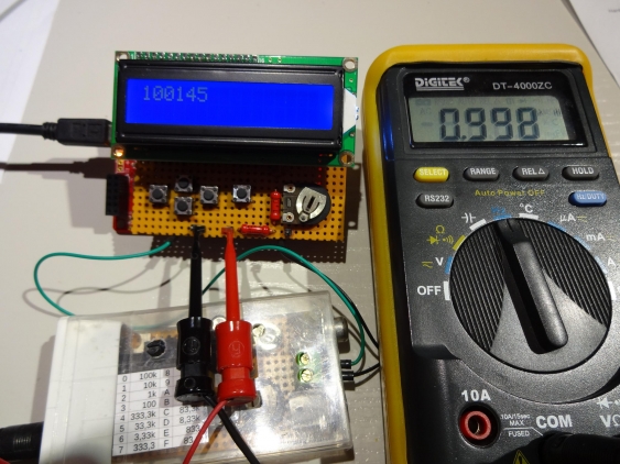
This time I’m using a LCD shield, so the setup looks a bit nicer than before.
The nominally 1 kHz clock used to drive the PWM is measured as 9.98 kHz (the DMM shows MHz), which is why the measured frequency (I’m using a 100 kHz signal this time) is higher than it should. But when calculating the expected result (10*100,000/9.98) we get 100,200. So the measured value is only 0.055% off. Looks like my frequency generator and the DMM seem agree about their frequency.
Again, I put the project archive up for download. Remember, its for learning only, don’t use it in production…
I have not really decided what to do next. Since the full implementation needs more digital resources than the PSoC4 can provide, I need to move over to the PSoC5. This would involve some smaller changes since the fixed-function components look a little bit different there, as well as the clock system.
But I might also add a proper input circuit to the counter, using a comparator with configurable threshold to enable measurement of sine waves (or other real analog input signals).
So stay tuned…


