« Calibrating an old Weston 1234 digital panel meter
| Main |Migrating the frequency counter to PSoC5 »
Old memories, old electronics kit and a new contest
I started my career in electronics (just a private one…) when I was a kid, more than 20 years ago. Growing up in East Germany meant that possibilities and access to e.g. components or tools were rather limited. One of the most useful items for learnings was an electronics kit which I used for many experiments, and which was and important tool to gather an understanding of what’s happening in an electronic circuit.
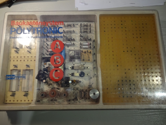
So I was really delighted when I found, several months ago, this electronics experimenters set on my parents attic (while cleaning out some of my old stuff still stored there):
This was too precious for me to throw it away (there are too many good memories connected with it), even though its more than 25 years old. and I thought that maybe may son also uses it one day to learn electronics…
MJLortons contest
When I then came around around to Martin Lortons [December competition}(mjlorton.com/forum/index.php?topic=441.0) I remembered what I did as first experiment when I got this kit as a present: not blinking a lamp (LEDs where kind of expensive back then…), but building a small radio. And then it occurred to me that may I can kill two birds with one stone: participate in the competition and have fun with my son. So why build a radio, again, and have him play with it? Surely this would fun - who didn’t like to listen to the first self-build radio?
So I started to look deeper into what was left from the set - after it all it was dormant for more than twenty years… So lets have a closer look at it:
Looking at the experimenters set
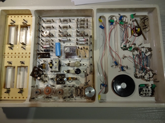
Its official name is “Baukastensystem Polytronic” (modular building blocks Polytronic - the latter work a combination of ‘polytechnic’ and ‘electronic’), and came in three different modules (A, B and C). Each module had a different theme, and they are build on top of each other.
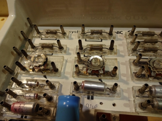
Each component is mounted on kind of a plastic tray, which can then be mounted on the base plate. There is a diverse set of components available:
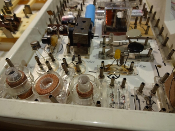
Starting with resistors (fixed and variable=, capacitors, but also a relay, some transistors, and even coils for RF experiments:
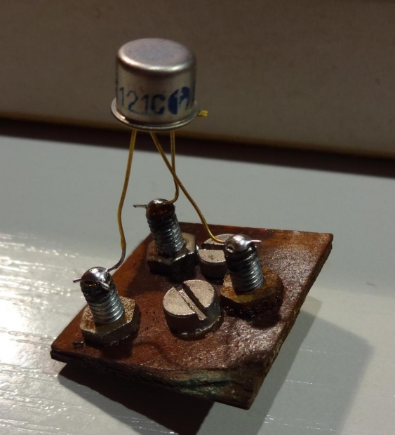
One can see here that I replaced one of the transistors (probably because the original one released the magic smoke…), but I even made my own trays to add more transistors:
They do look ugly, but work :) I used FR-2 as base material, and M4 screws as connectors. Unfortunately they suffered from the long storage time and corroded a little bit. But that could be cleaned with a cleaning pencil.
Building an audion receiver
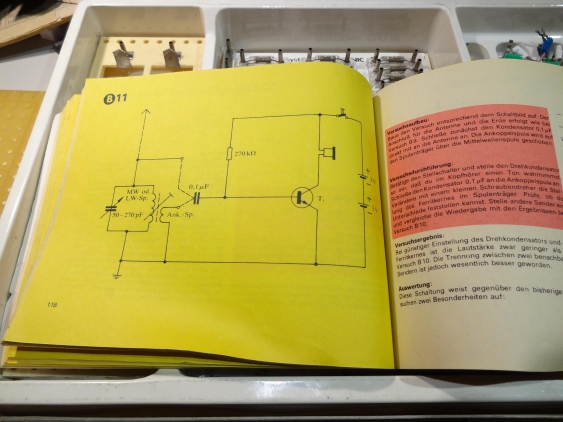
The manual (its more like a lab book) contains multiple experiments regarding AM receivers. Starting with a simple diode receiver (“crystal radio”) they get as advanced as one could expect when using just two transistors. I decided to go with the “Audion receiver”, as it promised to get the best reception (by compromising the audio quality). Its schematic is still simple:
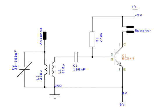
On the left we see the LC resonant circuit used for tuning. I measured the variable cap as between 30 and 300 pF and the coil with about 230 µH. This gives a tuning range from about 600 kHz up to 1.9 MHz which covers the whole medium wave band (except for the lowest parts).
The second coil is used for attaching to the signal without putting too much of a load to the resonant circuit. Next comes the transistor which acts both as rectifier (or “envelope detector”) and amplifier. The 270k resistor is used for biasing the transistor (so its working as class A amplifier).
I drew the schematic also in DesignSpark PCB (download):
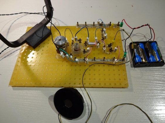
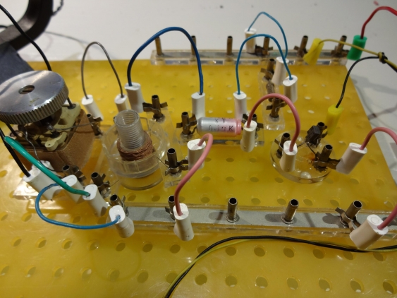
Build up on the carrier board it looks just a little bit messy - kinda like on a breadboard, just larger (and with more wires):
And a closer look:
Can you hear me?
But when I tried it for the first time, there was – nothing. Just static in the speaker. So I went error-hunting. Checked the cables twice, measured all components, even the transistor. After all, they are more than twenty years old now. But everything was fine. So I decided to verify with my stationary radio the frequencies for the radio stations. But alas - there was nothing there too! After then trying to look up radio station frequencies I found out that the last station I could have received in my area has been switched off a year ago. Bummer.
So the plan of having fun with my son listening to radio station on a home made radio was gone. But I wanted at least having something to show for this contest. But without radio station to receive its getting difficult to build a radio…
Creating something to listen on
Fortunately for me the experimenters set shows, just some pages before the radio did build, how to build a small radio transmitter. Its transmit power is not large enough to send via air, so it needs to be connected to a radio with a wire.
I decided to build a version with transmits a constant tone. Using a microphone and at the same time trying to listen that it got received on the other side is difficult…
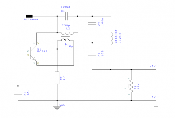
The schematic for the transmitter looks like this (DesignSpark PCB download):
Its using a rather clever design which combines a audio and RF generator. The latter is formed by the LC circuit (L2 and C4) together with L1, R2 and C1 (and Q1 naturally). Its signal is modulated by the audio generator, formed by Q1 (again), R1, C2 and C3 which form together with the speaker coil another LC circuit, just with much lower frequency. The audio generator shapes the amplitude of the generated RF signal (at about 1MHz) with a 1kHz signal (depending on R1).
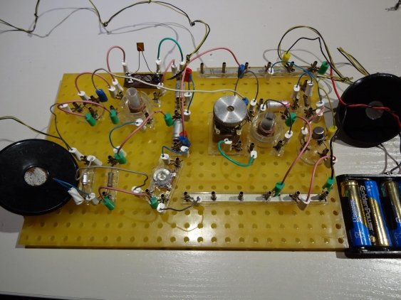
I connected the transmitter output and the receiver antenna input via a small capacitor, and was successful with the first try (which normally is a bad sign…). I could hear the tone in the receiver speaker, and turn it on and off by powering the transmitter or not.
So even though I was somewhat successful in the end, its rather sad that one of the most interesting and satisfying electronic experiments I did as a kid is just possible anymore today. I gues this is the price we pay for all the technological advances of the last three decades…
