Migrating the frequency counter to PSoC5
In the last article I ended with the question whether to move on on the PSoC4 and add some features, or to move over to the PSoC5 before doing so. Since I would need a DAC for the next stepping (adding a comparator with variable trigger level), I took a deeper look at the PSoC4 data sheet.
It comes with two DACs, but since they are current output DACs, I would need an external resistor. Since the LCD shield doesn’t leave me with a way of adding components on top of the Pioneer kit, I decided to move the project over to the PSoC5 (which has two voltage output DACs).
Differences between PSoC families
Since the project now moves to a different PSoC family, it seems a good place to talk a little bit about the different PSoC families.
The oldest PSoC family is the PSoC1. It is the one Cypress started with, and is the most different of all. Using a M8 CPU core, its the slowest of all series (in term of computing speed). It uses a different tool chain in form of PSoC designer, which exposes much more of the internals to the developer. This makes development more difficult, but also allows greater flexibility.
All other series use the PSoC Creator tool chain, the PSoC3 with a Keil compiler for its 8051 core, and PSoC4 and PSoC5 the gcc ARM compiler. The series number roughly follows the raw CPU core speed, but the series differ much more in their other capabilities. PSoC5 is still the top-of-the line series, with the fastest CPU core, most programmable digital blocks and largest selection of analog components. In terms of available components (both digital and analog) PSoC3 is next. PSoC4 is positioned as low-cost alternative to both of these, so it has fewer programmable digital blocks, and also as not all other peripherals known from the older PSoC series. (I expect this to change with later series of the PSoC4).
Especially the the number of UDBs is a reason to switch this project over to the PSoC5 - the frequency counter needs two 24-bit-counters, and the currently available PSoC4 just contain enough UDBs for one of them. I could have used a PSoC3 too, but I have a nice development kit for the PSoC5 here (a CY8CKIT-050) which I will use. This board is larger than the Pioneer kit (about three times), but it comes already with a LCD on board, and has an additional prototyping area (and some buttons and LEDs).
Migrating the project
To migrate the project over to the PSoC5, one just needs to select another target device (a CY8C5588 in the case of my DevKit). When no components available only for the previous device have been used, the code should already compile fine.
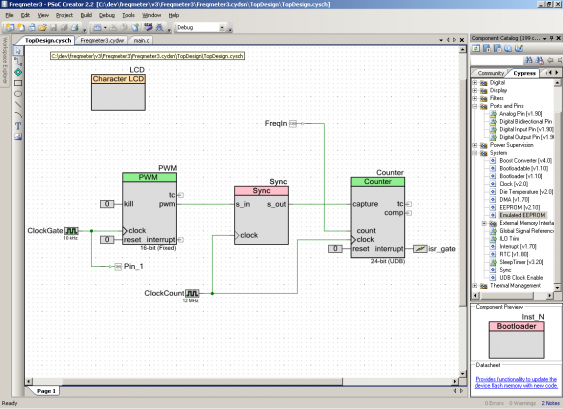
Since we used some fixed-function components, which are special to the PSoC4, they need to be replaced with the PSoC5 equivalent. Thats why the PWM component now looks different - I again used the FF version instead of the more universal UDB component. Apart from that, the schematic for the counter and also the code stay the same.
Since now I don’t use the LCD shield anymore, but the LCD available on the DevKit, I can also use the normal LCD component instead of the multi-port version. API-wise they are compatible, but the standard component gets configured with adjacent pins instead of being able to configure separate pins for each line.
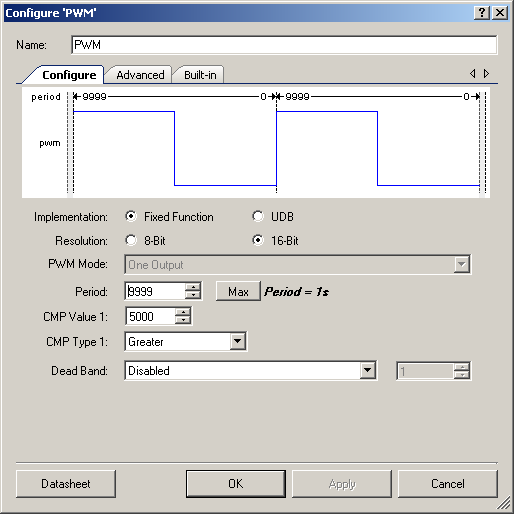
The PSoC5 version of the PWM component looks different than it did for the PSoC4. On the 4, there is a fixed function block (TCPWM) used for timers, counters and the PWM, whereas on the 5 one can select either between a pure PWM fixed function block or a UDB implementation.
The PSoC4 version is more generic (since the configuration dialog is re-used also for timers and counters) and the UI reflects that. On the other hand, the PSoC5 PWM is more capable - e.g. it can handle two PWM outputs in varying configurations. So these options need to be present (and the UI then needs to be tailored to these specifics).
For the same reason the Counter component dialog looks different (except when using the UDB based counter on the PSoC4).
Apart from these minor differences when working with some components one can work the same way with both PSoCs. There is still some signal synchronization needed (and there are some differences when we would try to mix clock and data signals). But the PSoC5 has much more digital and analog resources available, which will gives the flexibility for the next steps in this series.
Conclusion and outlook
So the migration between different PSoC families is rather simple. The components usually are compatible between the different families. All the changes in the hardware are hidden within them, so one normally doesn’t need to care.
Having the project now moved over to PSoC5, the next article will focus more on the analog side. I will add a proper input stage, allowing measuring analog signals. For that, the comparators will be used, and a DAC for setting the trigger level.
Again, I put the project archive up for download. Remember, its for learning only, don’t use it in production…

