« Wireless power contest - strategies for charging a battery pack, part 3
| Main |Two times is not enough - Measuring the performance of the wireless power demo kit part 3 »
Two times is not enough - Measuring the performance of the wireless power demo kit part 3
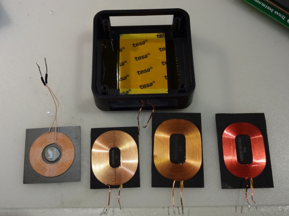
Wuerth Elektronik was so kind to provide me with some additional coils to be used with Qi-compatible transmitters (and receivers). I actually asked, when receiving he offer, just for a specific one. But someone at Wuerth thought it might be better to send two for every single one they have in stock (which is four different types).
So now I have to decide which one is suited best for my purposes - and that means another round of measurements…
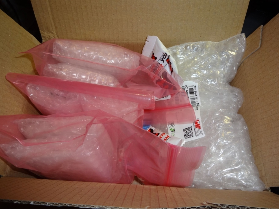
Since Wuerth did package them really good, 8 coils take significant room:
But this packaging is really needed, since the coils come with ferrite backing, so they might actually break in transport otherwise. And there was the additional shipment of gummi bears, so even my son was happy about all of that :)
Measurement setup
Since I had to measure 4 different coils this time
I did not want to repeat the whole set of different measurement series as I did for the original coil. I just went with no load and then a load current of about 500 mA, since that reflects about the load I expect to have later on. As usual I measured how much of a horizontal offset I could have before the output power starts to drop. And as well I measured the vertical distance I could achieve (with and without load). In addition, I also checked how much of a horizontal offset I could have in another direction (perpendicular to the normal direction I used), to see whether the orientation has any influence.
So here are the raw measurement values I took (using the 4 coils from left to right), first for current and distances:
| Coil & load | Distance | Offset (charge) | Offset (startup) | Tx current | Efficiency |
|---|---|---|---|---|---|
| 3737 - no load | 1 mm | 11 mm | 8 mm | 105-130 mA | 0 % |
| 3737 - no load | 3.5 mm | 12 mm | 11 mm | 140-230 mA | 0 % |
| 3737 - no load | 10 mm | 13 mm | 10 mm | 340-550 mA | 0 % |
| 3737 - 500 mA | 1 mm | 12 mm | 9 mm | 600-625 mA | 83-80 % |
| 3737 - 500 mA | 3.5 mm | 13 mm | 10 mm | 625-690 mA | 80-72 % |
| 3737 - 500 mA | 10 mm | 13 mm | 10 mm | 700-1080 mA | 71-46 % |
| 3830 - no load | 1 mm | 12 mm | 11 mm | 97-145 mA | 0 % |
| 3830 - no load | 3.5 mm | 12 mm | 12 mm | 105-250 mA | 0 % |
| 3830 - no load | 10 mm | 13 mm | 12 mm | 175-620 mA | 0 % |
| 3830 - 500 mA | 1 mm | 11 mm | 10 mm | 680-730 mA | 73-68 % |
| 3830 - 500 mA | 3.5 mm | 12 mm | 12 mm | 660-800 mA | 76-62 % |
| 3830 - 500 mA | 10 mm | 13 mm | 12 mm | 715-1250 mA | 70-40 % |
| 4832 - no load | 1 mm | 12 mm | 10 mm | 105-205 mA | 0 % |
| 4832 - no load | 3.5 mm | 13 mm | 11 mm | 130-330 mA | 0 % |
| 4832 - no load | 10 mm | 14 mm | 11 mm | 250-750 mA | 0 % |
| 4832 - 500 mA | 1 mm | 12 mm | 9 mm | 640-680 mA | 78-73 % |
| 4832 - 500 mA | 3.5 mm | 13 mm | 12 mm | 640-810 mA | 78-62 % |
| 4832 - 500 mA | 10 mm | 14 mm | 11 mm | 690-1205 mA | 72-42 % |
| 4832(red) - no load | 1 mm | 10 mm | 8 mm | 105-140 mA | 0 % |
| 4832(red) - no load | 3.5 mm | 12 mm | 10 mm | 120-240 mA | 0 % |
| 4832(red) - no load | 10 mm | 13 mm | 10 mm | 250-640 mA | 0 % |
| 4832(red) - 500 mA | 1 mm | 10 mm | 8 mm | 640-670 mA | 78-75 % |
| 4832(red) - 500 mA | 3.5 mm | 12 mm | 10 mm | 640-730 mA | 78-68 % |
| 4832(red) - 500 mA | 10 mm | 12 mm | 10 mm | 700-1100 mA | 71-45 % |
The second table shows the electrical characteristics, and the maximum distances I measured (this time also for the original coil as well):
| Coil | 3737 | 3830 | 4832 | 4832(red) | original |
|---|---|---|---|---|---|
| inductance (µH) | 10 | 16.7 | 12 | 12 | 10.5 |
| resistance (ohm) | 0.16 | 0.29 | 0.16 | 0.33 | 0.2 |
| max current (A) | 4.5 | 2 | 3 | 1.55 | |
| offset sidewards | 11 mm | 12 mm | 13 mm | 11 mm | 13 mm |
| max. vert. distance 500 mA | 11 mm | 15 mm | 15 mm | 15 mm | 15 mm |
| vert. distance startup no load | 11 mm | 13 mm | 11 mm | 12 mm | 11 mm |
| vert. distance startup 500 mA | 10 mm | 11 mm | 11 mm | 11 mm | 10 mm |
Results
From the first table one can see that especially the the efficiency differs between the coils, depending on the conditions. For example the smallest coil (in 37x37 mm size) is the best one for short distances, whereas the 38x30 one is best for larger distances. The larger 48x32 mm coil seems best when needing larger horizontal offsets (but the red wire version of it seems worse in that regard, even though its a little bit more efficient).
What I also saw is that the direction of the horizontal offset doesn’t matter. Regardless of the direction, the distance where energy is still transmitted is the same. I guess this is because the receiver coil is smaller than the transmitter coil, and the important factor here seems to be the distance between the centers of the two coils (and the transmitter coil is a round one).
I noticed two other effects: one is that with some of the coils the output voltage dropped much more (for a short time, before stabilizing again) when the coils got moved than with the other ones. This was most noticeable with the 38x30 mm coil. Second thing is that none of the new coils showed the high-pitched noise that got noticed with the original one.
For my project, where the horizontal offset is rather important, the 38x30 mm coil looks like the best candidate. It provider better efficency than the original coil (even though its the worst of all the four), while working in a wide range of distances very well. Even when starting into a load of 500 mA it can handle distances well above 10 mm. So its the one allowing the most flexibility for placement of the two coils while still delivering good performance.
Outlook
Since Wuerth also has a new selection of transmitter coils available, and provides them to the contest participants even before they are available for buying, there will be a fourth round of measurements. But for the next installment I plan to talk a little bit on cell protection. For this project this means an under-voltage lockout circuit.

