Low-voltage continuity tester
One of the most-often used tools on an electrings workbench, right behind the digital multimeter, is the continuity tester. Whether you want to verify that your solder work was fine, or are looking for a shot where there shouldn’t be one, the continuity tester is the go-to-tool. Turn it on, probe in your circuit and wait for the buzzer to go off. Its as simple as that.
But they most of them share a problem: their probing voltage is too high. They are designed to even turn on a LED, so most meter use a probing voltage of 2 volts, and may go up to 3 V. In my collection only my old and cheap DT-4000ZC uses a probing voltage of 0.44V, all the others are around 2.9V. Why is that a problem, and what can we do about it?
The problem with the voltages
The problem with these voltages are the semiconductors. As long as you are using the continuity tester on a bare PCB, or with passive components (resistors, capacitors or even wires) you are fine. These behave as they should, and the tester shows whether there is a connection between two points or not.
But when semiconductors such as diodes, transistors or integrated circuits enter the scene, this changes. A diode starts conducting current at 0.6V (depending on the direction of current), a schottky diode starts even at 0.3V. A bipolar transistor also starts conducting at 0.6V, but it depends also on how you connect it. For integrated circuits it gets even more complicated, but since they are build from transistors, diodes and resistors (more or less) the 0.3V from the shottky diode are a safe guess for when they start conducting current too.
So when you are probing with 2V or more, on a populated PCB probably one or more of these diodes, transistors or ICs will start conducting, and the tester signals you a short when there is none. Maybe you can get lucky and find this out when you reverse the test leads and then no short is signalled. But this is not guaranteed.
Another problem is that there are more and more circuits that just cannot handled the voltages. For example FPGAs typically use core voltages of both 2.5V and 1.8V - testing such PCBs with 2.9V will just damage them.
Now what to do?
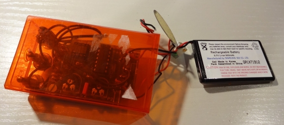
So the solution to all of this is just using lower voltages. And my go-to continuity tester has been designed to wotk this way. I bought it as an assembly a long time ago (I think it might be about 20) from Conrad and use it since then. Being a kit means you won’t get a nice enclosure, and the one I found to fit was a TicTac-box:
(Orange taste, btw.). I remember that the original enclosure was a lot bigger since I used a 9V battery back then. But when I found myself with a spare LiIon battery from an old phone, I used that one and a smaller enclosure. I used a M3 screw to hold the PCB in place, and I was too lazy to disassembly everything for this phote. Sorry!
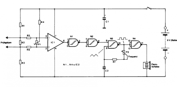
So how does it work? Fortunately Conrad provides the complete manual for download on the product page, although its not available in English. So here is the schematic (for the actual component values please look at the manual, or even beter: buy the kit, its not that expensive):
The circuit consists of two parts. On the left we see an operational amplifier (a good old ‘741) configured as difference amplifier. P1 is trimmed so that with open leads the positive input is just below the negative input, and with shorted inputs its just above. Since there is not feedback, the output will then change from low to high voltage. The voltage divider formed by R1, R2 and R3 is configured so that the voltage on the test leads is just below 2mV (yes, milli-Volt!). When the output goes “High”, the generator formed by N3 and N4 (which are part of a CD4093) is enabled, and the piezo speaker is turned on.
The only drawback this circuit has is that your test leads need to be really clean. Otherwise their contact resistanceis to high and the tester won’t detect any shorts at all.
So thats it - one of my most used tools. Now just go out and buy one for yourself…

