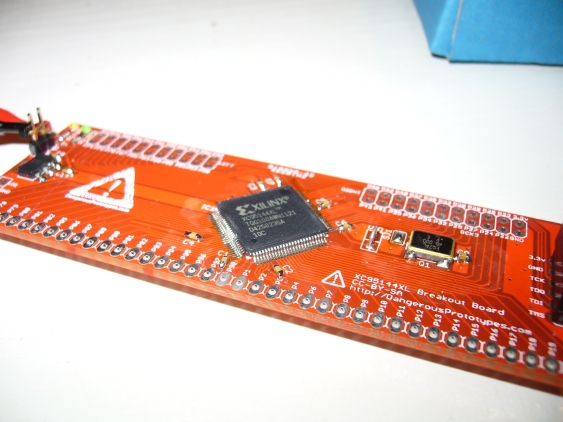
Free PCB Build - XC95144XL Breakout Board
After finishing my last free PCB build I got a new coupon from Dangerous Prototypes. I decided to go for a xQFP prototype board this time. Unfortunately it went missing somewhere in the postal service, and there weren’t any more left. So I decided to go for a XC95144XL CPLD breakout board instead, which DP send out promptly.
I decided to add the crystal oscillator too, since I might use it for my frequency counter project. Doing this with a normal soldering iron is rather difficult, since it’s in QFN style with the pads underneath and on side of the package, having no leads. But the cap near it was even more difficult, because it is located so near to the oscillator. This is also true for most of the other components - many of them a way too close of each other. The most *1117 regulators want to have tantalum capacitors, which are in larger packages than 0603 (they don’t like ceramic caps because the ESR is too low with them). So I went with a ceramic cap, and it doesn’t seem to cause problems so far.
Soldering the TQFP100 package was way easier than I thought. It lined up properly with the second try, and the last side was a nearly perfect drag soldering example (but I needed some cleanup on the other sides).
I bridged Vio, since I don’t intend to use it with other voltages than 3.3V.
But it worked without hiccups from the beginning, so I should not complain too much :) My test project was just a frequency divider, which divides the 48 MHz from the oscillator by 224, which gives nice 2.3 Hz on the green LED (connector to P73). One can see it lit up in the back in the final image
I have no header soldered in yet since I’m not sure whether I need it for a breadboard or for a full circuit. So right now it’s just the JTAG and power headers.
