Implementing the frequency counter part 2
So it’s finally time for the second part of my implementation. It took a while longer than intended, part because I changed more than originally intended.
Main goal was to connect to CPLD to a micro controller, to read out the counter results. The easiest way for the MCU would have been to provide a serial data stream (like SPI). But since we have 48 bits to transfer, I would need a 48 bit shift register - and there aren’t 48 registers left in the XC9572XL. So I did go an easier route and just build up a large multiplexer.
Reducing the number of signal needed
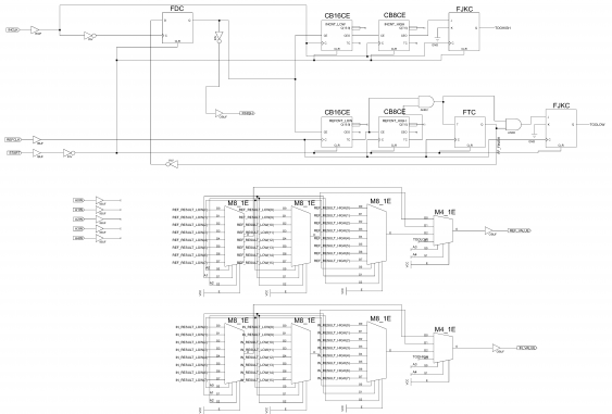
I added, for each counter, three 8-bit multiplexers, which are in turn connected to a 4-bit mux. This results in needing 5 address lines, and 2 output lines. The TOOHIGH/TOOLOW signals are connected to the 4-bit mux, so I end up in needing 9 control lines and 2 clock inputs.
Unfortunately I wasn’t able to use only a single output line for the muxes (using a 8-bit mux instead of the two 4-bit ones), because then ISE WebPack couldn’t place all the logic in the CPLD. Right now I’m using 58 macro cells, and 52 registers. The timing reports says I can go up to 53 MHz of clock speed.
So it might be possible to add a 5 bit counter, and replace the address lines with a clock. This would give something like a 2-bit SPI output. But for now I can live with using 4 lines more.
First tests
When testing this to read data by the MCU, I run into a strange problem: the results were right for lower frequencies (up to about 10 kHz), but were too low with higher frequencies. It took a while to find the reason: I had cascaded the two counters incorrectly. I should have read the data sheet better: all clock inputs of the different stages are connected together, and connect the overflow output (TC) to the enable input of the next stage (CE). Otherwise the overflow of the next stage happens too early.
What I also did was reworking the trigger and gate logic. My main reason was to improve the frequency up to which this circuit works - I was hoping to reduce the internal delays. I failed with that, but at least I was able to remove one of the flip-flops, and the two AND gates gating the input clocks (the latter one was the reason I hoped the maximum frequency would go up, since this meant I could not put the inputs on the global clocks). When trying the same circuit on a XL95144XC (my Dangerousprototypes free breakout board), I found out that the pin placement has influence on the speed. Allowing the Xilinx compiler to decide about the placement shaves another nanosecond from the delays, and the maximum speed goes up to 56 MHz. But for building this up on my breadboard, I’m quite fixed with my pin placement, so I cannot use this.
My final circuit
The resulting circuit looks like this:
So I ended up with freeing some internal resources, and on the way changed how the signaling of a finished measurement cycle works. before, the FINISH signal would go to 1 with the start signal, and going to 0 signals the finished cycle. But now, it stays 0 and goes only to 1 when the real measurement starts. So the MCU code needed to be adapted to that.
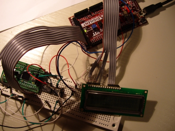
Speaking of the MCU: I’m using a ChipKit MAX as controller. A 3.3V LCD is used, so no level converter is needed. The final setup involves the ChipKit, the breakout with the CPLD (which basically looks the same) and the LCD:
The ChipKit also delivers 5V to the CPLD board.
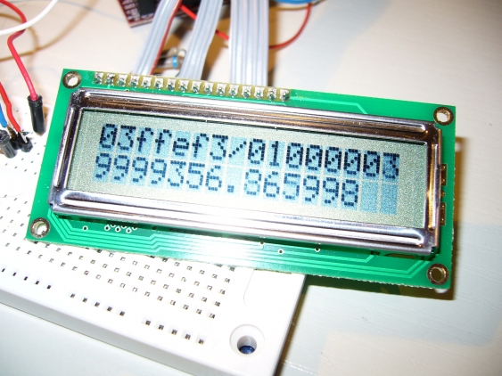
As before, I’m using a 40 MHz reference clock and measure the frequency of my 10 MHz oscillator.
And some results
It is a little bit off, but both oscillators are specified with 100 pm accuracy, and the result is 70 ppm off, so I’m well within spec.
Now what are the parameters we get? I can measure frequencies up to 40 MHz (the reference clock) and down to 1.19 Hz (CLKref/(2^25-2)). The update speed varies a little bit, but will be between 1.2 and 2.4 Hz (it gets over 2 Hz with any reasonable frequency). The precision is 0.06 ppm, regardless of the frequency. For my 10 MHz test oscillator, this means a resolution of 0.6 Hz - which is what I’m seeing on the display (when the result changes, it changes by 0.6 Hz). But this resolution doesn’t change with lower frequency, which means a 10 Hz input will be measured with one millionth of a Hz precision. But since my reference clock is only accurate to 100 ppm, the accuracy of the result is not better than that. But it still means you can measure e.g. audio signals with a rather high resolution, and still have a decent update rate.
There are several ways to change these characteristics:
- increasing the reference frequency shifts the measurement range upwards
- it also increases the refresh rate (which is twice the lower bound of the measurement range, in the best case)
- reducing the bit-width of the counters increases the lower bound of the range, and therefore increases the update rate
- but it also lowers the precision
The ChipKit code is as follows:
  #include<LiquidCrystal.h>

  #include<stdlib.h>

  #define REF_FREQ 40000000.0

  // define pin connections
  #define START 23     // P38
  #define FINISH 25    // P37
  #define IN_VALUE 27  // P36
  #define REF_VALUE 29 // P34
  #define A0 31
  #define A1 33
  #define A2 35
  #define A3 37
  #define A4 39


  // RS=72
  // EN=73
  // D4..D7=74..77
  LiquidCrystal lcd(72, 73, 74, 75, 76, 77);

  void setup()
  {
    lcd.begin(16,2);
    lcd.print("starting up");

    pinMode(START,OUTPUT); // START
    pinMode(FINISH,INPUT);  // FINISH
    pinMode(IN_VALUE,INPUT);  // IN_VALUE
    pinMode(REF_VALUE,INPUT);  // REF_VALUE

    pinMode(A0,OUTPUT); // A0
    pinMode(A1,OUTPUT); // A1
    pinMode(A2,OUTPUT); // A2
    pinMode(A3,OUTPUT); // A3
    pinMode(A4,OUTPUT); // A4

    digitalWrite(START,1);
  }

  unsigned long ref_cnt=0;
  unsigned long in_cnt=0;

  boolean toolow=false;
  boolean toohigh=false;

  char buffer[14];

  void read_counter()
  {
    ref_cnt=0;
    in_cnt=0;

    // shift in all values, MSB first
    for (int i=23;i>=0;i--)
    {
      digitalWrite(A0,i&1);
      digitalWrite(A1,i&2);
      digitalWrite(A2,i&4);
      digitalWrite(A3,i&8);
      digitalWrite(A4,i&16);
      ref_cnt=(ref_cnt<<1)+((HIGH==digitalRead(REF_VALUE))?1:0);
      in_cnt= (in_cnt <<1)+((HIGH==digitalRead(IN_VALUE))?1:0);
    }

    // now read overflow/underflow flags
    digitalWrite(A3,1);
    digitalWrite(A4,1);

    toolow =(1==digitalRead(REF_VALUE));
    toohigh=(1==digitalRead(IN_VALUE));
  }

  void loop()
  {
    lcd.clear();
    while (true)
    {
      toolow=false;
      toohigh=false;
      int error=0;
      // send start
      digitalWrite(START,0);
      delay(1);
      digitalWrite(START,1);

      while (1==digitalRead(FINISH))
      {
        // wait till measurement has started for real
      }
      long time=millis();
      while (0==digitalRead(FINISH))
      {
        long now=millis();
        if((now-time)>2000)
        {
          error=1;
          break;
        }
      }
      lcd.clear();
      if (0==error)
      {
        if (toolow)
        {
          lcd.print("too low");
        }
        else if (toohigh)
        {
          lcd.print("too high");
        }
        else
        {
          read_counter();
          ref_cnt=ref_cnt+0x1000000;
          double freq=(double)in_cnt*REF_FREQ/(double)ref_cnt;
          sprintf(buffer,"%f", freq);
          lcd.print(buffer);
        }
      }
      else
      {
        // no input signal
        lcd.print("timeout");
      }
    }
  }
Especially the output is not really polished - it should handle the actual precision of the measurement instead of printing the full number with all decimals.
There is also the WebPack ISE project for download.


