CD Player current savings
Recently, we bought a kid-compatible portable CD player for our son (basically it is larger and a little bit more rugged than a normal one, and has smaller buttons to be easier to use). We were just sick of hearing 6 hours “Bob the builder” during the car trips… When it arrived, we put a set of batteries in and tested it. After that, we left it until the skiing vacation. Fortunately we tested it the day before we started - the batteries were dead. So we thought “maybe we forgot to turn it off” and put a new set in. During the vacation, we mostly left it connected to its power supply. So it ran from batteries only on the car trip and during the night (when we unplugged the supply). Unfortunately, on the day we drove back the batteries were dead as before - and this time we knew it was switched off properly.
Getting to the bottom
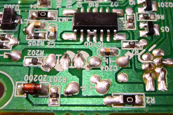
So some investigation was in order. When I hooked it up to the lab power supply and measured the standby current, I was surprised - 24 mA is way too much for any battery powered device. So I started investigating the board for potential problems. The first obvious one was a short on one of the ICs - look at the top of this picture.
Just removing this bridge reduced the current consumption to 12 mA - which is still to high. So I started reverse-engineering the circuit. One of the first places after the power supply connector was the diode which can be seen on the bottom left of the same picture. It turned out that is was zener-diode based voltage regulator. And since it is always on, it also draw always current. And the 820 ohm resistor used for biasing it might not seem large - but it also draws about 6 mA.
A real solution
So I replaced it with a proper LDO (a MCP1702-3303), which only draw about 2 micro-amps in standby. This brings us to a standby current of 6 mA, which gives about 4 weeks of battery life in standby (there is still a part of the circuit not powered by the 3.3V). Since I still considered this to be too short (1 year would be OK), I looked further.
Reverse-Engineering proved to be too messy, so I tried to find a solution to switch the player off completely when not used. But I did not want to ass just another switch in the battery lines. First, it looks kind of messy, and second it is way to easy to forget it. I wanted to use the existing power-on switch to trigger the additional circuit.
The existing SPST switch just connect the internal circuit to ground - so it could be used to drive PNP transistor. This can be used to switch it on, and since the same switch is used by the player itself, it will also turn on. But then the whole player will turn off again when the button is released. Fortunately there are several places in the players circuit which will react to the power-on signal. One of these can be tapped and hold the circuit in its on state. So only when the button is pressed for the second time, the player itself will turn off, the signal will go low, and then the new circuit will turn it off completely.
A proper auto-power-off
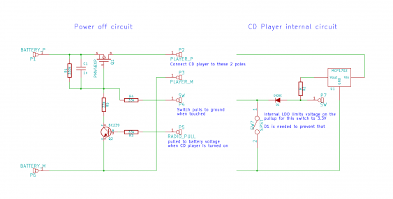
This results in the following circuit:
The left part shows the new power-off circuit. I used a P-channel MOSFET instead of a BJT, since the latter has easily 1 Volt (or even more) as emitter-collector saturation voltage when it needs to conduct 1 ampere (which is the peak current consumption). The NPN transistor inverts the tapped signal from the player. The 1 nF capacitor is just there to prevent accidental turn-on due to interferences or external noise.
And some rework…
But unfortunately this didn’t work out as expected - the player still consumed the same amount of current. It turned out that the power-on switch is connected to a pull-up, which in turn is connected to a 3.3V LDO (the one I added before). Even though the signal is connected to the LDO output, it still pulls down the signal to 3.3V - which is low enough to turn the MOSFET mostly on. So I split the signal on the PCB holding all the buttons, and added a diode in-between. This prevents the LDO pulling down the line, while still allowing the button to pull down the signal.
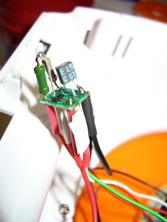
Since the only P-channel MOSFET capable of driving 1 amp I had around was in a SOT23 package (a PMV48XP), I build this up on a SOT23 prototyping board (thanks to SmallRoomLabs for the Sockisop. The FET did go to one half, the remaining 3 holes take up the BJT, and all the passives go in-between:
After that it only took some tape around it, and now I can safely use the player without removing the batteries all the time…


