Pimping a kids night-light
When you have kid at home, there is no absence of project ideas. When we got night light for our son two years ago, the first thing I did was replacing the batteries that came with it rechargeable ones (which is good idea for all things which are in regular use). But still it was a hassle to always recharge them - the battery compartment is secured with a screw, which will break down eventually.
So when I won a set of breakout board over at tronixstuff, I soon had an idea for one of the modules: take the RGB LED and convert the plain white night light into a colored with - with automatic cycling through all of them. And while I was working on it, I also though I could add a Li-ion battery, so I could charge it directly without opening it up all the time (there was already a connector for a power supply, but it’s kind of a bad idea to have cables in a kids bed during night).
Controlling a RGB LED
The RGB LED is controlled by a WS2801 constant current driver. Driving this one is rather easy - it can just be hooked up to a SPI port, and then it expects 24 bits of data to be send (one byte for each red, green and blue). The only important thing to remember is to pull the CLK signal low after the transmission for more than 500 microseconds, because otherwise it won’t transfer the data to the output registers.
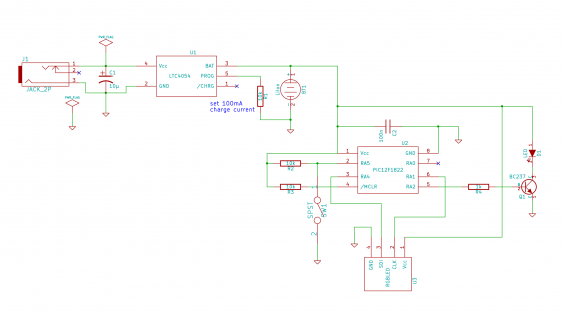
So to control this, a MCU is needed. I used a Microchip PIC12F1822, which comes in an 8-pin package. I’m just using its SPI capability. But what was important is that I can use the SPI connection and the ICSP connections in parallel (I don’t like it when a port output needs to be connected to another output on the PIC programmer). So I used the alternate pin locations for the SPI port.
Software for a color cycle
The software part is rather simple. The PIC gets initialized to a core clock of 500 kHz (using the internal RC oscillator), which saves current and is more than fast enough. The timer is configured to wake it up every half a second. The program maintains the internal state of where in the color cycle it currently is, and knows the current brightness values for the three colors. With every wakeup, it changes the brightness a little bit, and when needed advances the cycle where it is right now.
The basic cycle is to ramp up one color while another one declines its brightness. The declining color goes dark when the rising color reaches half of its target brightness. After that, the color rises to its full brightness and then starts declining. When it reaches half of the target brightness again, the next color will start rising its brightness, and so on.
The target brightness is not the full one. The WS2801 is instructed with a maximum value of 64, which is one fourth of the maximum value. This results in a light which is still bright enough (remember - the light is usually in the bed) and reduces the current consumption so the battery lives a little bit longer.
Low battery protection
Every minute, the PIC will measure the current battery voltage. It does this by measuring the voltage of the internal 2.048V reference, while using Vcc as ADC reference voltage. This means that with declining battery voltage, the measured value increases (because the measured, constant, voltage gets larger with respect to the non-constant reference). When the measured voltage reaches a certain threshold (699 - corresponding to 3.0V) the PIC clears the LED, stops the timer, disables all interrupts and goes to sleep - effectively switching itself and the night light completely off. This serves a low-battery protection.
The PIC also switches itself of one hour after it has been starting - there is no need to have the light running for the whole night when kids has fallen asleep. The last feature is a select switch so our son can choose whether he wants the colored light or the white one (which is much brighter, and sometimes he prefers that). The switch gets read by the PIC, and then it either enables the existing white LEDs (via a transistor, and it disables then the RGB LED too) or the RGB LED with the current color values.
Putting everything together
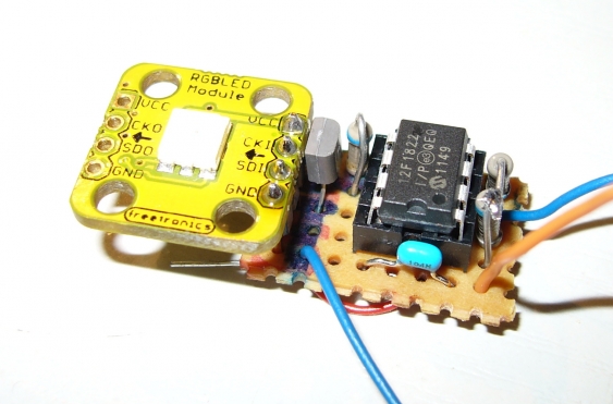
I build the whole thing on a small perfboard, which is only about twice as large as the PIC itself. The RGB LED module is connected by a pin header, which I just soldered into both boards. That way, I could use the existing mounting hole of the module to mount both boards together into the night light (using an existing hole for the screw).
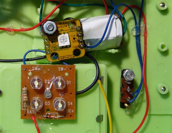
In the middle the original white LEDs can be seen. The switch on the right select between RGB and white mode. It was not possible to glue it in its place - the plastic used for the night lights case did repel both super glue and hot glue. Therefore I needed to use some small screws to hold it in place.
Even though the schematic above also features the Li-ion charger, this will be covered in the next installment.


