Playing with a TCXO
When I started working on the frequency meter project using the PSoC, I thought it might be a good idea to get better accuracy than the normal crystal oscillator could deliver. After all, it should be more accurate than the usual gated timer version you can find on Google. A crystal oscillator (like the SG531-40 I have in my parts bin gives an accuracy of about 50-100 ppm - so it can be 0.01% off (so at 10 kHz it could be off by 1 Hz). On the other hand, the temperature-compensated oscillator (TCXO) I bought on ebay (a TCO-986) is specified with 0.5ppm - so its more accurate by a factor of 100. The TCXO also has a much lower drift over temperature and time, so it will stay accurate over a longer time. So the idea was to put this oscillator on a breakout board (it comes in SMD package) and then use it for the frequency meter.
Clipped sine wave is not CMOS
Unfortunately the TCXO doesn’t give a TTL or CMOS output, but a clipped sine wave. And with a specified peak-to-peak voltage of 0.8V it cannot be used to drive a logic input (be it a CPLD or a MCU). So this needed a conversion circuit.
Another problem: the TCXO gives a 26 MHz output. And since I don’t own a scope with a large enough bandwidth to look at the output signal directly (the iMSO-104 has only 5MHz), it was difficult to see whats happening. That meant that I was relying on guesswork when designing the circuit.
First level converter experiments
My first thought was just using a comparator: one input goes to the TCXP output, the other one to an adjustable reference voltage. The connect the output to a divide-by-ten counter (a 74LS90) to get 2.6 MHz, which I can then measure with my multimeter (which goes up to 4 MHz). The reference voltage was to be adjustable between 0.1 and 2V, since the data sheets does tell only the amplitude, but not the average value of the sine wave (the TCXO runs with 3.0V, so I assumed the output is either referenced to 1.5V or to 0V). I used a LT1394 as comparator, because it has a fast response time (7 ns - the 115 ns for the usual LM311 are not fast enough for 26 MHz) and has a TTL output. It doesn’t come in a DIP package, but a SO8 breakout board solves that problem.
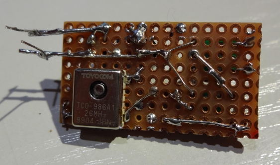
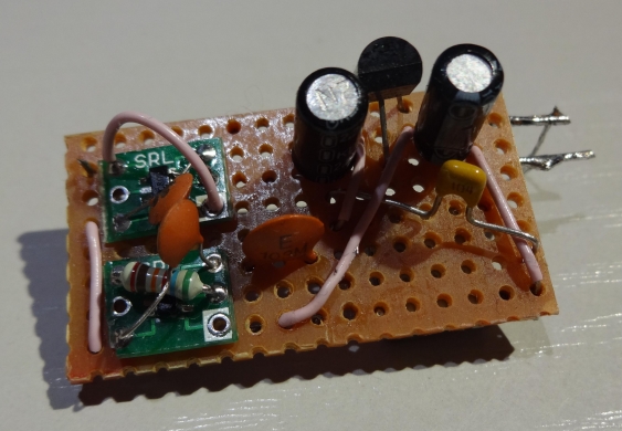
I used a small perfboard for all the components, which then should act as a breakout board for everything. Basically its then like a normal crystal oscillator running at 5V, just a little bit larger (and more accurate…) The TCXO is on the underside of the board, because its in a SMD package, and everything else (LDO, caps, comparator) goes to the top.
Circuit debugging
Unfortunately it didn’t work - the output of the ‘LS90 stayed high all the time. I started by debugging by verifying with a crystal oscillator (one of the SG531s) that the Divider indeed worked. Then I did the same for the comparator (by just feeding the square wave into its input). Everything worked as expected, so the culprit was either a non-working TXCO, or that my plan with the comparator does not work.
Google to the rescue
Without proper tools its difficult to debug. I could not look at the signal (lack of scope) nor measure anything (a DMM is virtually useless for such high frequencies). So I resorted to the recommended solution. This resulted in some examples of how to properly convert a clipped sine wave signal into TTL (or CMOS) using a 74HC04 buffer. Since I had none in hand, I used a 74HC00 instead (one input goes to Vcc, the the other one then works as inverter). This worked like a charm in the first try.
But looking at the data sheet shows that there is no big margin in the transition times for this chip when working at 26 MHz. A pitfall also lies in the fact that the two different count inputs of the ‘LS90 have different maximum frequencies (it consists of a 2:1 and a 5:1 divider, and the latter can only go up to about 16 MHz).
A proper level converter
So for generating a proper signal, I changed the HC00 to a 74LVC1G04 single gate (its available in SOT23-5 package, and goes up to several hundred MHz), and I don’t need a full blown 14-pin IC here. To get a signal with proper 50% duty cycle, I added a LVC1G80 single DFF as a 2:1 divider. My assumption is that the inverter doesn’t generate a signal with exact 50% duty cycle, so the 1:2 divider will generate that. But hopefully the duty cycle is stable so that there is no additional jitter introduced.
On the right side the wires can be seen which I added as breadboard contacts. As LDO a LP2950CZ-3.0 got used (it doesn’t require the use of low-ESR ceramic caps, so I could use normal electrolytics).
While investigating the problem I found another project utilizing a TCXO - and it uses a comparator to generate a square wave. Interestingly it uses GND as compare level - this would imply that the output signal of the TCXO can go to negative values. I could confirm that this works (after I found the recommended solution using the inverter gate). But I will still go with the official solution provided by the TCXO manufacturers and use an inverter gate. Just playing safe here, and the number of components is the same anyway.
So now I have a hopefully really accurate clock reference available and can start further work on the frequency meter (even though I don’t need it for the first iterations). The second TCXO I scored will most likely go into a waveform generator (making use of a DDS chip, so I will need to scale the frequency up using a PLL). If I ever encounter the need to get even more accurate, I will either lock the TCXO to a GPS one-pulse-per-second signal (it has a trim input) or try to get a rubidium standard from ebay. But for now its sufficient…

