Cypress PSoC introduction
I already mentioned the Cypress PSoC family of chips several times in this blog, but I never came around to explain a little more about them. But since I’m currently working on my frequency meter project which will get implemented with a PSoC5, I figured I can use this as a good example. So this posting will be start of a series. It will start with an overview - what are the Cypress PSoCs, which families are available, and what can be done with them. I choose the frequency counter already used before as an example. The first part will be an implementation as known to most people, which I will then further refine.
So, what is the PSoC?
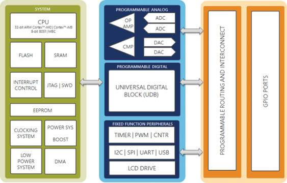
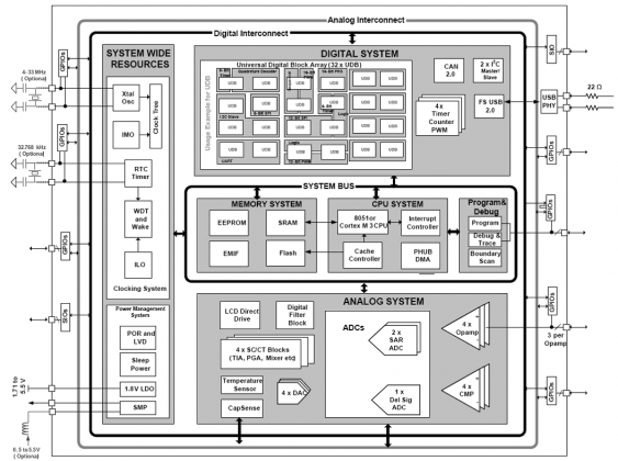
The acronym stands for “Programmable System on a Chip”. Most easily, you can imagine it as a MCU (depending on the series, a M8, 8051, Cortex-M0 or -M3) surrounded by programmable digital blocks (like a CPLD or FPGA) as well as programmable analog blocks (like ADCs, DACs or Opamps), which can are connected via a flexible routing system.
No, its not a FPGA
In contrast to FPGAs which can be configured to behave like a MCU (e.g. with an AVR core) it is a real MCU core (a Cortex M3 in case of the PSoC5) with all the support one can expect (for programming and debugging, e.g. a SWD interface). The programmable digital blocks are a combination of CPLD functionalities (configurable gates and registers) with a small arithmetic unit (ALU). So this forms additional small CPU cores, since each of these blocks can execute small programs. Third component are the programmable analog elements. The PSoC allow flexible routing between all of these parts (there are OpAmps, PGAs, SC/CT blocks, Multiplexers, ADCs and DACs).
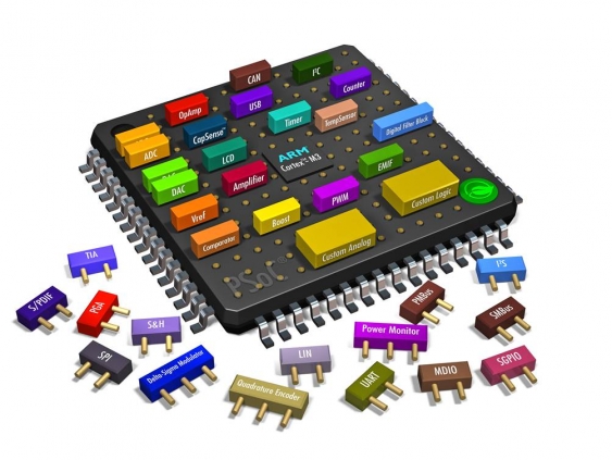
And last but not least all of these blocks can be combined to create new, high level functionality. For example the delta-sigma-ADC is not a native component of the PSoC 3 and 5, but is formed by combining multiple smaller components (an amplifier, a delta-sigma modulator and a decimator). So if needed one can use these low-level components to build other components. The same goes for digital components. There are for example fixed-function blocks for PWM available. But if there is a need for more functionality (or just more PWM outputs than possible with them), additional PWM blocks can be created from digital blocks.
A good IDE helps with programming
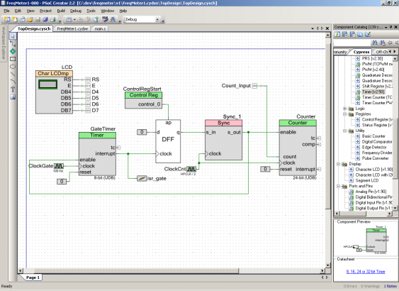
All of this capability if captured by the IDE which goes by the name “PSoC Creator”. Apart from the usual functionality one can expect, such as code editor, MCU programming and debugging support, there is a schematic editor available:
This editor allows to configure all the internal blocks (digital as well as analog ones) in an easy way. There is no need to learn cryptic register names and constant to configure, this is done via dialogs which explain really well how the component can be set up. For some components such as PWM there is even a good visualization of what the effect of the current setup is (e.g. given the clock frequency, period, duty cycle and PWM type it shows how the output signals will look like). This speeds up development, and reduces the chance of errors.
The schematic editor is also used for connecting all the components together. Given the large number of available functionality and components, this allows to create a large part of the desired functionality from within PSoC Creator, without needing external parts. Creator frees the designer from working with the routing manually (this is only needed for the PSoC1 family), so its more like a FPGA in that regard (except that also handles the analog world).
So much for an introduction. In the next part I will show how to implement a simple frequency counter. This will still be one that most people recognize, as it will look like one done in pure hardware (mostly at least). But it serves as good start into the wonderful world of PSoC, and it will be enhanced in the other parts to come…


