« Wireless power contest - strategies for charging a battery pack, part1
| Main |Small update regarding the Numato FPGA boards »
Wireless power contest - strategies for charging a battery pack, part 2
In the last part of my wire less power contest article I had a look at options for charging a battery pack by dividing it into single cells for charging. Since all the options proved to be too complicated for my purposes, I will take a look at how to charge the battery pack at once.
As already mentioned in the last part, the charging circuit needs to make sure the single cells are not over-charged. That means they are not subject to higher voltages than specified, and are not charged anymore after being fully charged.
What a balancer does
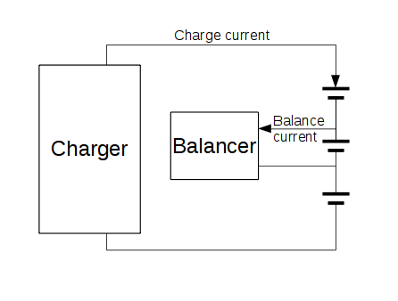
Since all cells in a battery pack are in series (though in larger packs they might even be in parallel in addition), it is not possible from the outside to control the current flowing through a single cell. This is the reason for potential overcharge of some cells. To allow better control of the charge process, battery packs sold as such (e.g. for RC models) come with a so-called ‘balancing connector’. This connector gives access to the connections between the cells, which are hidden in the pack otherwise. Packs like for laptops don’t have that, since they have this circuitry inside.
Having now access to all the cells, the charging circuitry still can only have the same current through all the cells. But since it can measure the voltage for any cells, it can determine the charge state for each. If a cells is found to be fully charged, the balancing process can start. In that mode, the charging current is diverted from the cell, so its not charged further.
I show here, for clarity, the balancer for just one cell. The charger itself handles the whole pack - controlling and measuring the charge current, and checking for the end-of-charge condition. The balancing circuit the diverts the charge current away from the cell.
How does it work
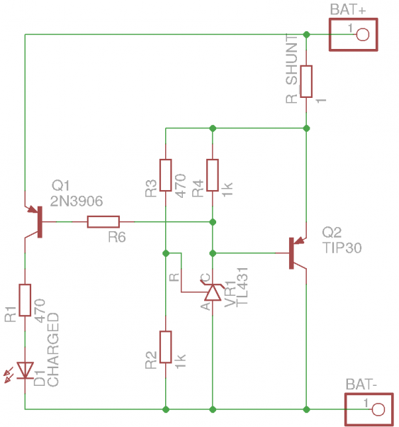
The basic principle I described above should be known already - its that of a shunt regulator. So the simplest solution for a cell balancer is using an integrated shunt regulator, like the well-known TL431. But since it can handle only current up to 100 mA, the typical cell balancer adds two elements to it: first a transistor to increase current capability, and second a notification mechanism to detect end-of-charge. Such a balancer looks like this:
The current diverted from the cell gets dissipated in the transistor Q2 and the shunt resistor. The LED lights up when the shunt is active, meaning the cell is charged. This LED can be part of an opto-coupler, which can be combined for each cell to detect when all cells are charged. The combination R2+R3 should be made of some trim-pots to set up the right voltage.
Other options for balancing
The principle I outlined here is called ‘passive balancing’. The balancer is active only when charging, and just looks at a single cell to ensure it doesn’t get over-charged. And then the energy gets just dissipated as heat, so its wasted.
But there are also active balancers. Not only can they be active during dis-charging a battery pack, they can also distribute energy between the different cells (hence they’re called ‘active’). They work like switch-mode regulators, and draw current from one cell to charge another cell with it. That way, the balancing can even be done during discharge - when one cell has more capacity than the others, this can be transferred over to use the full capacity of all cells equally.
Unfortunately the chips doing this are designed for larger battery packs (6 to 12 cells), so they come in rather large packages to accomodate all the connections (like 44-pin SSOP). They also need a good amount of external circuitry, so I ruled them out for this project.
There are also a number of passive balancers available (like the BQ3060 or the BQ77PL900 from TI). But they share some common restrictions. Due to thermal limitations, they can only handle limited balance currents with their internal FETs (most can do 10 mA, some can do 50 mA). And when used with external FETs (which most support), they can only balance a single cell. Many of the balancers also require the usage of an external controller (a MCU) for configuration and monitoring. So this also gets to complicated for my project. So I will stay with a simple passive balancer.
What I will be using
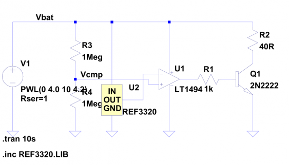
The TL431 needs a minimum current of 1 mA when in regulation, and about 5 µA when in non-regulating state (this is the combination of the current through the diode part of the regulator and the current for the reference input). Since the TL431 is also not exactly accurate (0.5% for the the best grade), I’m thinking of using a different solution. I will use a low-power voltage reference, together with a low-power operation amplifier to build the shunt regulator. Together they will draw about half of the TL431 current, and are accurate enough even without manual trimming.
As LTSpice simulation, this looks like this (though the actual parts are different, this was my first go on it):
Outlook
But this circuit will need to wait a little bit, since the next article will be about the charger itself.


