Building an ATX power supply
Using ATX PSU as basis for a lab power supply is an easy way to get started when building a lab power supply. It solves all the hard parts about wiring the transformer and the voltage regulation stuff, and basically leaves only the wiring. Especially when one needs some high-current PSU, this a nice way to get a simple solution. So I had this on my ‘projects to do’ list for a while (and even started to get some components). So when I stumbled over a nice project by an italian electronics hobbyist I was intrigued. Francesco Truzzi did a great job not only on creating a nice breakout PCB, but also on adding some additional features. So when he offered to send his surplus PCBs to readers of his blog I took my chance.
The PCB offers the usual breakout for all the voltages generated by an ATX PSU (3.3V, 5V, 12V and -12V). In addition, it spurts a LM317 to create an adjustable output voltage from the 12V line. And then Francesco added a TPS2513 and two USB connectors to have two USB charging ports that can deliver up to 2 A of charging current. The chip handles signalling the attached device that its safe to draw that much current.
I had most of the components available to populate the board, so I just ordered a ATX connector that fits the PCB (originally I thought it might be possible to solder the wires directly to it) and the TPS2513.
The build
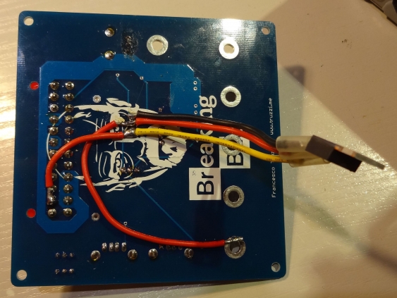
Since some of the traces on the PSB are rather thin, I replaced them by wires (incidentially one from an old ATX PSU…). I also did not use a LM3178, but a LM350 instead to get higher current output. The ATX PSU can easily deliver 10 amps on the 12 V line, so why not make use of that? But that also meant I needed to use an external heatsink, so the LM350 got also connected with wires:
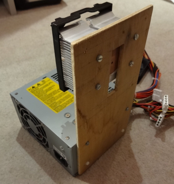
Since the heat sink I wanted to use (an old CPU heat sink) was smaller than the PCB I could not mount it directly there. So I used a wooden board, mounted the heat sink on one side and the PCB on the other:
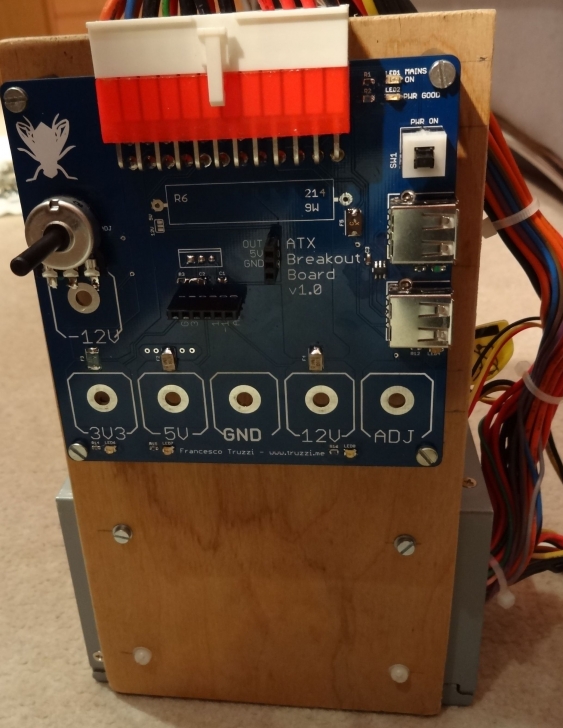
The same board also mounts everything to the PSU itself. I did not find a potentiometer that to fit into the provided footprint. I only had some with 5mm pitch but the footprint was for 2.5mm (which I think is rare). But you can solve that with some wire too:
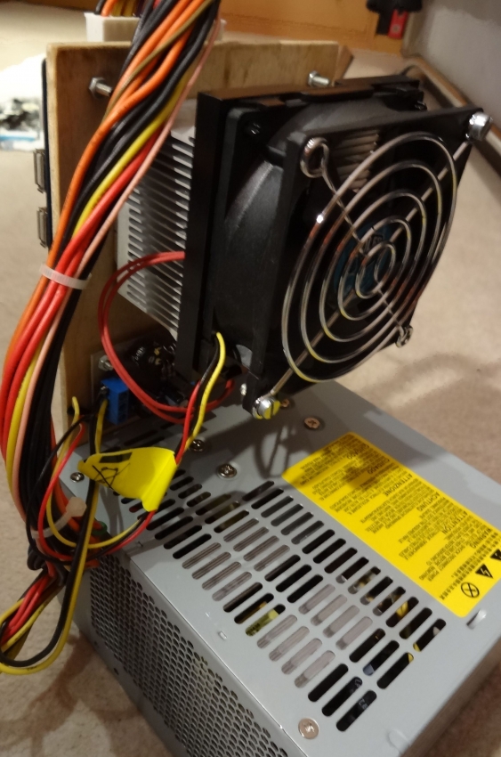
Last but not least the heat sink got a fan mounted. Its speed is adjusted by temperature, using a curcuit out of a old c’t magazine (german article). That should allow to use the full 3A current capability of the LM350.
The only missing items at this point were the banana jacks. The are mounted with nut and washer into the holes. Only the one for the adjustable output gets a solder wire on it (since the trace is too thin). The ATX PSU serves as base so it doesn’t tumple over and sice the breakout sits on top there is no risk of accidentially creating shorts by stuff laying around on my desk.
I might replace the SMD PTC fuses by trough-hole ones. In SMD size, the maximum current one can get is about 2.5A. But in PTH, one can easily get 7A or even 10A fuses. And since the PTCs were the parts that I already got for my planned project, I might as well use them. The existing SMD footprints are large enough to accomodate even the larger through-hole PTCs, it seems. Doing so would mean that I can get up to 7A from this PSU and can drive larger loads.


