SPG8640-based crystal frequency generator
One of the tools that belong in every electronics toolset is a frequency generator. There are many design out in the internet that to build your own generator. Starting with a simple 555 timer (or even just transistors), moving up to the venerable XR2206 and ICL8038 and then maybe up to the MAX038 they typically can generate since, triangle and square wave over a wide frequency range.
But they all rely on manual frequency setting, and their accuracy is in the single digit percent range (maybe as good as 0.1%). If you want to have a stable frequency source, you need a crystal based oscillator - and that typically means using a DDS chip.
When I needed a small frequency generator for a project several years ago, I did neither had the time nor the skills to build something like that. But I had in my parts box a nice chip that seemed perfect for a small tool - the SPG8640BN.
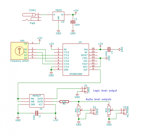
This small chip is a crystal osciallator combined with a configurable divider. The specific ‘BN’ version has a 1MHz oscillator, one divider up to 1:12 and one divider up to 1:107sup>. So it can generate an output from 1/120th up to 1MHz. Nice. Configuration of the output frequency happens via several control pins. The first three select the base frequency, as the control the 1:12 divider. The selectable dividers as 1, 2, 3, 4, 5, 6, 10 and 12. The other three control pins control the second divider, and select the division stage - with each stage dividing by 10. So we have 8 different base frequencies, and each can span 8 decades.
Frequency selection
I did not want to use a microcontroller to control the generator, so I needed another way to control the output pins. When I found a binary decoder switch in my parts box, I had an idea for a neat solution:
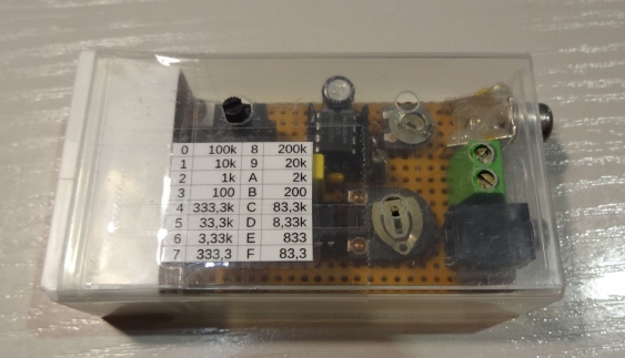
The decoder switch has 16 positions, and each position connects the 4 outputs to the common connection according to the binary number. So I used the upper two bits to select the base frequency, and lower two bits for the decade. When selecting the values carefully, this can give a usable frequency range from 333kHz down to 83Hz.
Output circuit
I wanted to be able to use this generator in a variety of situations. So I designed the output to give me both a TTL output and signals usable for audio. Since I had a couple of MAX627 drivers in my parts box, I decided to use one of them. They are actually MOSFET drivers, but their current capability makes them suited to drive low-impedance loads. One of the MAX627 channels drives the TTL output, the other one two audio channels.
For the latter, I added two trim pots to adjust the audio levels. One audio channel can be adjusted from 0 to 2.5V, the other one up to about 1V. When an actual head phone is connected the signal is even lower since the head phone impedance is in parallel with the trim pot.
Building it
As usual I took some perf board, and found out that the whole circuit fits in an old tic-tac box. The frequency selection switch has an axle, so it can be used from the outside. For the trim pots I drilled small holes so they can be adjusted with a screwdriver. As power supply I added just a 7805 with a barrel jack.
Since then its an invaluable tool for me. Be it checking some audio circuit or a digital one, it always comes in handy. I even use it when a circuit just needs a square wave - its faster than building up a 555 timer…
The only limitation so far is that it cannot drive 3.3V circuits. When I would rebuild it, I would add a level shifted output too. And probably a LDO for the power supply to use it directly from the circuit under test.

