Review - Tektronix TBS1052B-EDU oscilloscope
As part of the Forget me not challenge in the Element14 community, I got an oscilloscope from Farnell to be used as part of the design challenge. Due to a communication mishap it was advertised as being the 200 MHz version, but in the end all participants got a TBS1052B-EDU. Now that I had some time to use it and get some hands-on experience with it, its about time to write a review.
Initial impression
The unboxing was unspectacular. The package was lighter than expected (somehow I still think good test equipment must be heavy), but Farnell did a good job here. The scope comes with its two probes, a CD with the software on it, a calibration certificate and a German power cable (that was a nice surprise, since the package came from the US).
First task to do was looking at the firmware and searching for updates - there was even a reminder in the box to do so. The scope came with version 2.02, and just the day I received it Tektronix release version 2.52 (though the download came active only 4 days later). The release notes indicates some minor improvements, but I actually found one bug in the older FW: the ‘snapshot’ functionality was already in the menu, but ended just in an error message. The firmware version 2.52 solved that.
On problem came up during the update, though. The manual (and the help) stated that the new firmware should just be named “SOMETHING.TEK”, and in the download it had a version number identifier in its name. Unfortunately the scope never did recognize that file as being a firmware update, even after I deleted all other files on the USB stick. Only after naming the file “TBS1KB.TEK” the update worked properly.
On the CD that comes with the scope there is the manual, but it might be better to download it because then it matches the current firmware version. Also on the CD is the OpenChoice program which can be used to store screen shots and waveforms retrieved from the scope. This software is not specific for the TBS1000B series, but its used for all Tektronix scopes. The last item is the course editor - that one is specific for the EDU series of scopes. Its used to create you own educational material that can be put on the scope to be used by students (or other people learning how to use one). I did not test the latter one, since I don’t really need it at home :)
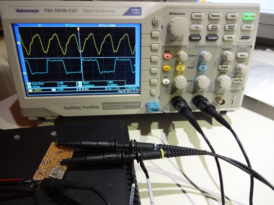
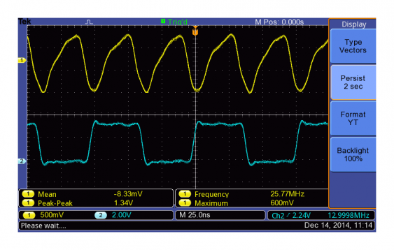
My first test was to finally take a look at the signal coming out of my TCXO board. The 26 MHz signal was way too fast for my iMSO104 scope, so I needed to work blind back then. So lets have a look now:
On the top is the signal from the TCXO, on the bottom the output from the 1:2 divider DFF. One can see now that the TXCO output swings well below ground, which caused my grief in the beginning. The 13 MHz digital signal looks quite clean. But there are already artifacts visible since the bandwidth of my model is only 50 MHz (and I did not compensate the probes yet when taking this picture).
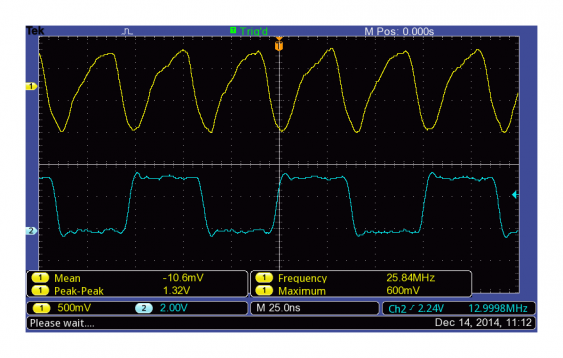
After compensating the probes, I took a screen shot of the signals itself:
The sine wave output now looks cleaner, but due to the bandwidth limitations the square wave output still shows some overshoot.
Daily use
When using the TBS1000B-EDU one of the first thing to notice (or rather: not to notice) is that its completely fan-less. That means there is no noise whatsoever, and the scope nonetheless stays rather cool. The power switch also seems to be a real one (instead of just a soft power-off), though I did not measure the power consumption when the scope is off. I like that its placed on top of the scope, because that way it cannot be turned off by accident (the Rigol DS2000 series has some button in a place where the user normally rests its hand while using some other buttons which is bad user interface design). On the other hand it means that its getting more complicated to place the scope in a rack because its hidden. But I guess one needs to have some room for air circulation on top anyways (and I don’t have a rack for it).
After turning on one needs to wait for about 35 seconds. Thats quite long, and it kind of makes the “I just use the scope to look at this signal” scenario difficult. But I like that the scope remembers the settings from last times, in most cases thats what I need. As long as the project I’m working on is still the same, I usually look at the same signals and so need the same settings.
The display size is OK given the screen resolution, and the menu doesn’t take too much room (and it can be turned off anyway). But when I use the scope on the bench I place it to my left. And then I don’t see the top row of the display, because the display frame gets in the way. And the top row is where some of the status data is shown. So it should be placed more in the back of the bench (or in a rack) to see the display completely.
What I find annoying is that when opening a selection menu (e.g. AC vs. DC input coupling) the scope always selects the first entry instead of the one currently active. Thats especially irritating when turning on and of multiple measurements, because the menu needs to be reopened every time and one needs to start from the beginning, instead of the last position. it also means that the highlighted entry (not that the highlighting is very visible anyway) does not match the current setting so one needs to look twice before starting to change something. (I have no screen shot for that, because sub-menus will close when doing so)
The probes are fine, at least to my. They are for 50 MHz, and are of 1:10 type. Whether the same probes will be delivered with the 200 MHz version is something to be seen - in that case I think its not a good choice. The probe cable is rather long, but its flexible enough not the be in the way when doing measurements. Sometimes I wish the ground hook and the hook on he probe would be smaller, but I guess its the usual size. I will see whether I can get smaller ones (at least for the ground hook).
The scope has a dedicated ‘print’ button, and can be configured not to print to a USB printer, but to store a screen shot on an attached USB stick. Thats quite handy, but storing the file takes about 20 seconds.
Some practical use cases
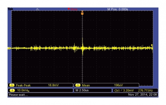
For some tests I used it to look at the output of some small power supplies I was experimenting with. I started with a classic LM317 regulator, and checked its ripple and noise figures. First I shorted the probe to ground and took a baseline for the scope noise:
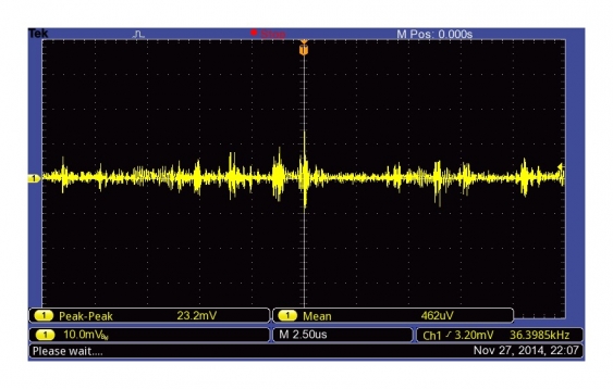
Next the LM317:
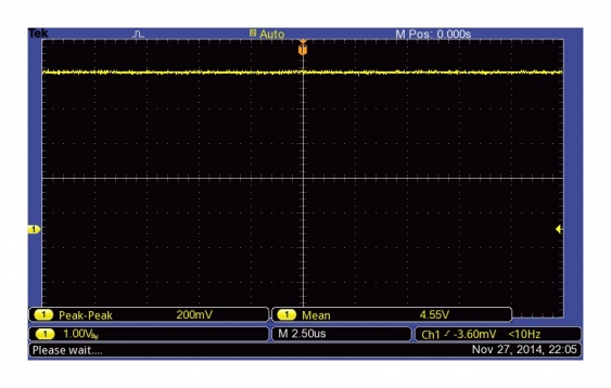
That looks not so much different, so ripple and noise of the LM317 are rather low. Note that I select AC coupling for that measurement - when using DC coupling the result looks different:
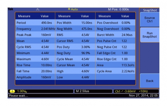
Using this mode there is all the DC part of the output visible, which makes measuring the ripple quite difficult. Next I took a measurement snapshot, which gives all the data that the scope can measure at a glance:
But it really is a snapshot - the signal cannot be seen in that mode. For that, the measurement mode can display up to 6 measurements.
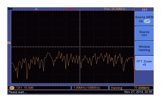
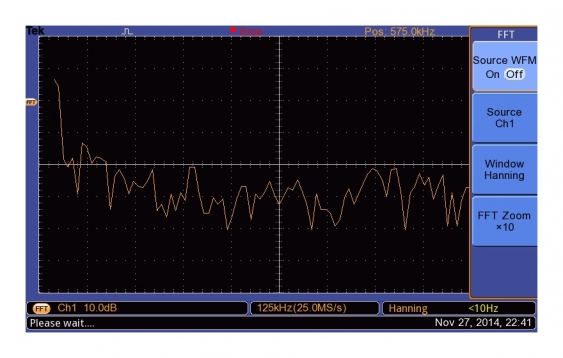
To get a better overview about the different parts of the signal, one can use the FFT functionality. In essence it calculates the different frequencies that make up the signal. It works kind of like a simple signal analyzer, just with much lower resolution. For the LM317, it looks quite flat:
which is to be expected - there is no real ripple and the noise figure is quite OK.
Testing some SMPS
Next test was looking at some simple switched-mode power supplies I had laying around:
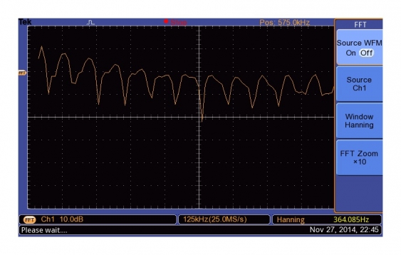
As FFT it looks a little bit workse than the ML317:
The second one looks even worse (the settings are the same)
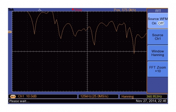
And the third one goes through the roof:
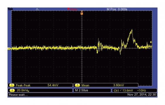
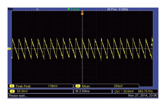
Last test was LMZ12003 Simple Switcher board I build a while ago. I had no real issue with it, but was curious to see what its output looked like. But I was in for a surprise when looking at the noise and ripple:
Something must be really wrong with that board - the ripple is supposed to be in the single digit millivolt range! It looks as if the output cap doesn’t work at all, so I need to verify that one.
Looking at the TCXO again
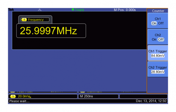
To have a look at the hardware frequency counter and some other features, I used the TCXO breakout again. It can be found directly under the ‘Function’ menu (and its the only menu item there).
It shows the frequency with 6 digits precision, and is specified with 50 ppm accuracy. Assuming that my TCXO is still within spec (0.5 ppm) the scope is sure within its range, even though it doesn’t show exactly 26 MHz (its about 10 ppm off). It can show one or two channels. But even when one channel is deactivated, its corresponding trigger level is shown in the menu. Its also worth to note that the trigger level cannot be changed with the regular trigger level knob, but must be set with the multi-function knob. (And the error message that gets shown when using the trigger level knob has a spelling error :) When disabling both channels, the counter screen disappears - so when changing between both channels one need to activate the second first before disabling the current one. That can be irritating.
The hardware frequency counter also seems to be the one showing the frequency for the trigger signal (thats the one showed all the time), so there is not always the need to use its separate screen. One can select the frequency measurement for both channels, but the the frequency sometimes is way off.
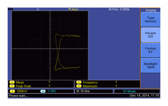
As last items I tested the persistence settings and the XY-mode. They are a little bit hidden in the ‘Utility’ menu, under the ‘Display’ sub-menu. The persistence can be set to 1, 2 or 5 seconds and to infinity.
When turning on persistence, the update rate gets noticeably slower. The signal looks like its using intensity grading, but the brighter trace in the signal is just the last update of the signal. But especially the infinity persistence is quite useful to see random spikes in the measured signal.
When switching to XY mode, the scope automatically selects a different timebase (seems to be 250 µS all the time), but it can be changed again.
Its also possible to turn on persistence in that mode to get a denser trace. The curve shown here is because the DFF output changes exactly when the TCXO sine wave reaches its lowest point. So the X axis runs through a complete cycle for each Y level.
Doing some measurements
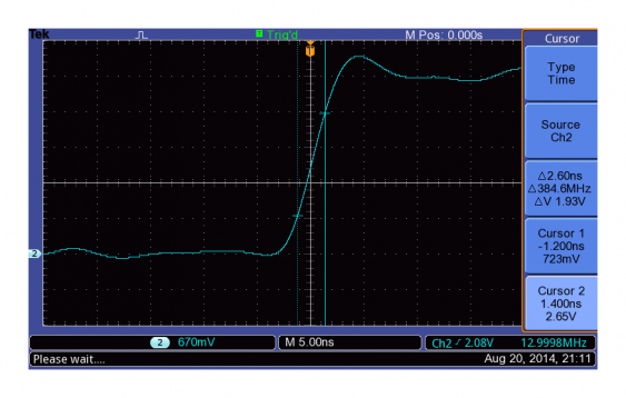
To make better measurements, there are cursors available. For example, one can easily measure signal rise times:
I selected ‘Time’ as cursor type, and positioned the cursors at about 33 and 66 percent of the signal.
Performance and limitations
So having looked at the scopes usability and some of its functionality, lets have a look at the more fundamental specs. As I already said, I got the 50 MHz entry version of the line. It goes up to 200 MHz, and the also come with double the sample rate (2 instead of 1 Gsps). So far everything looks fine. The triggering functionalities and the math and measurements function are also OK, the math seems to be a bit basic though.
The big limitation is the memory size. The TBS1000B-EDU series just stores 2500 samples per channel. And this is not up to par since several years now, This limitation makes analysis of most signals more complicated, since there is no way to go from an overview down to the depth of the signal without re-acquiring with a different timebase. One also cannot acquire multiple occurrences of the same trigger conditions (“segmented memory”), which could make analysis much easier too.
Conclusions
This scope is of really good quality, as far as I can see without opening it up. It feels sturdy and robust, and sure will have a long life. So it seems to be the right choice for its audience - people learning how to use a scope. It comes with most of the functionality I would expect from a scope. But its limited sample depth makes it a bad choice for people doing real signal analysis.
So, I would not recommend a hobbyist that scope. Given its price, there are much better alternatives in terms of functionality, performance and specs. Would the memory not be so limited, my verdict would be different probably. Its really good for learning how to use a scope, but its not the best choice for everyday use.
Its a really good upgrade compared to my iMSO104 scope, and it will be my everyday scope from now on. Despite me not recommending it a first choice to by, I see no need to replace it with another scope. Its still quite capable and will help me with my further projects.
