Comparing some oscilloscopes and their probes
Since my review of the TBS1052B-EDU scope I participated in yet another Element14 contest - and part of the provided kits was yet another scope. This time it has been a TBS1202B-EDU, the larger brother of my first scope. So I thought it might be a nice exercise to compare these two scopes with each other. Since this scope comes with 200MHz passive probes (in contrast to the 50MHz probes of the TBS1052B-EDU) I will compare them too. To make it a real shootout (and to even more insight) I will include my iMSO-104 scope too, which has a meager 5MHz analog bandwidth and 12 Msps sample rate.
Accessories and specs
The TBS1202B-EDU comes with the same set of accessories as the 50 MHz version, the only difference are the better probes. It came with a newer firmware than the other scope (v2.52) but I found out that again Tektronix had released an ever newer one. This time the firmware update went without problem, the downloaded file already had the right name.
The specifications of both scopes are nearly similar - which is to be expected as they are from the same family. The TBS1202B-EDU has a specified analog bandwidth of 200 MHz (instead of 50 MHz) and a sample rate of 2 Gsps (as opposed of 1 Gsps). Due to that the faster scope has a minimal time base of 2.5 ns per division (whereas the TBS1052B-EDU has 5 ns). Otherwise the input stage performance seems identical. The probes itself are “times ten” probes, and cannot be switched to 1x mode. The iMSO-104 comes with a switchable probe (1x vs. 10x). The datasheet says 100 MHz, but doesn’t state its capacitance (nor does it specify the input impedance or capacitance of the scope module itself).
Its interesting to look at the specified input signal rise time of the Tektronix scopes- its 2.1 ns vs. 7.0 ns which is not the 1:4 ration that one might expect (and we will see some real-world values later on).
Probe comparision
For comparing the probes I used the 200 MHz scope so its not the limiting factor. I took one 50 MHz probe and one 200 MHz probe, and compensated them with the channel I used them on (the 50 MHz probes are compensated to the 50 MHz scope). As test signal I used my TXCO breakout. It generates a 13 Mhz square wave signal which should be fast enough to show the scope limits. The 74LVC1G80 I’m using as divider has a signal rise time of about 0.9 ns so its also fast enough for my test.
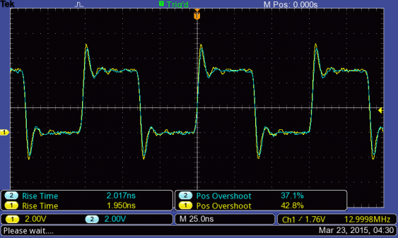
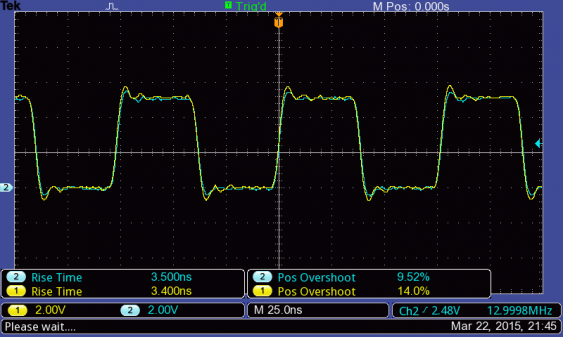
So lets look at the 13 MHz square wave signal, using the scope with 200 MHz bandwidth (the TBS1202B-EDU):
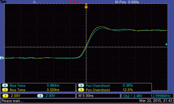
Yellow is the 200 MHz probe, blue the 50 MHz one. I added some measurements for better comparision. The signals actually look quite similar. The 200 MHz probe has a slightly faster rise time (which was expected) and more over-shoot. This puzzled me at first. But then I realized that I’m looking at a square wave signal, which is composed of many different frequencies. neither the probes nor the scope are fast enough to reproduce that truly, so we get only an approximation. Some over the overshoot (and ringing) is due to the cable and the probe connection (length of the ground lead), but the rest are the higher frequency parts of the signal. That means the larger overshoot of the faster probe is just because it can show faster signals which get already dampened with the slower probe.
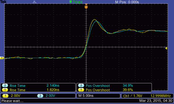
So lets look at a single rising flank to have an even better look:
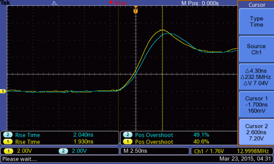
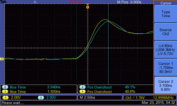
Now the larger overshoot and the better rise time of the 200 MHz probe are clearly visible. For exact measurements I used the cursors to measure the time from the signal starting to rise until the peak of the overshoot. This is not the real definition of the rise time (that would got from 30% to 70% of the signal), but its easier to measure and I need it for comparision only.
So for the 200 MHz probe that time is 2.6 ns, and for the 50 MHz probe its 3.1 ns. Not such a big difference. And we can see that the probe are only a smaller part of the analog performance when we compare that with the specification of the scopes from above (where the 50 MHz scope is specified with a rise time of 7 ns).
But we can see here that even a scope with 200 MHz bandwidth is not able to reproduce a 13 MHz square wave signal in full detail, because it misses the higher frequency parts of the signal. We will see further down what difference the scope itself makes.
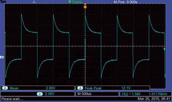
Now lets look at a probe with even lower spec. The probe for the iMSO-104 is specified with 100MHz, but I would assume its real bandwidth to be more about 5 MHz (to be in line with the iMSO-104 scope itself). Since the probe has a SMB connector instead of BNC, I needed to use an adapter. It had a corresponding SMB jack in my parts bin, and used a BNC-to-Banana adapter together with simple probes as adapter. I tested the BNC-adapter with the test leads for compensation (with the scopes 1 kHz signal) and it was fine. Same was for the iMSO probe in 1x-mode, but the 10x-mode looked very uncompensated:
Since the compensation is not in the cable, but in the iMSO scope itself, I could not correct it (except for trying to add a small capacitor directly to the banana jacks at the input).
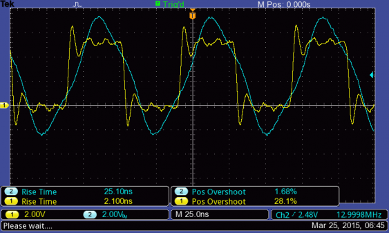
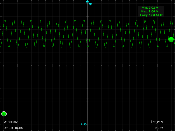
So lets look at the oscillator signal - first in 1x-mode (the yellow trace is still the one with the 200 MHz probe):
There is not much left from that square wave! Look at how much it over- and undershoots. The signal itself is not attenuated that much, but all higher frequencies in that signal are.
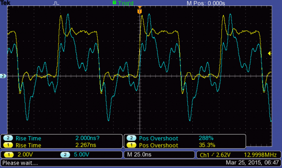
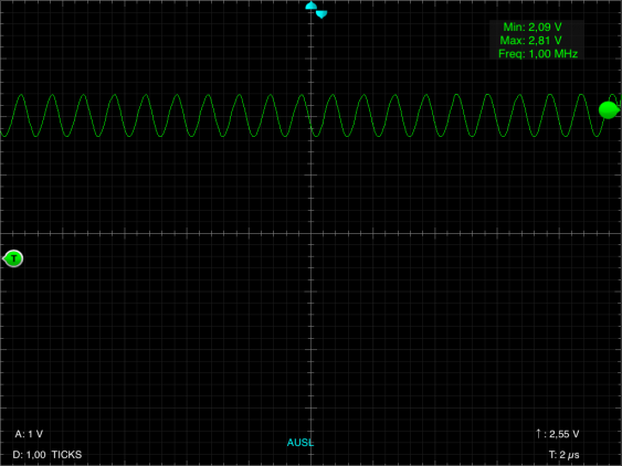
Lets see whether that gets better in 10x-mode - there should be a higher bandwidth available now:
OK, that looks at least a little bit like it could be a square wave. The signal attenuation is clearly visible. The overshoot from the non-compensation is also very visible here. (If you want to know why the 10x mode has a higher bandwidth: Dave Jones got you covered in EEVBlog #453).
So that probe should not be used with a signal above maybe 2 or 3 MHz, in 1x mode I would even go down to 1 MHz. Anything higher and you end up just with a rough estimation of the original signal.
Scope comparision
Having looked at the probe, its now time to compare the scopes itself (with their respective probes). I won’t show any additional screenshots for the TBS1202B-EDU since there are plenty enough. First test candidate is the 50MHz TBS1052B-EDU. Except for the lower bandwidth its specifications regarding the input stage are identical to the 200 MHz version. So lets have a look (the yellow trace is again the 200 MHz probe):
There is now less overshoot, and the measured rise time (by the scope) is also bigger. Lets zoom in:
Since the TBS1052B-EDU cannot go down to a 2.5 ns/div time base, the zoom is not as deep as with the faster scope. Be can see that higher frequencies as are in the overshoot are seriously dampened already. The rise time (as measured above) is about 7.5 ns - and its the same for both probes. The faster probe still shows a somewhat higher overshoot so its still dampening higher frequencies less, but its less pronounced now. But we can see that the scope stays true to its specified rise time of 7 ns.
Its still not bad, I would trust even the 50 MHz scope with such a signal. But now lets have a look at the iMSO-104 scope. Its analog bandwidth is 5 MHz, and it has just 12 Msps sample rate. So it have serious problems with a 13 MHz signal - but how much?
Ouch. Does the 10x mode look better?
No, not really. The signal got reduces from a 5 V peak-to-peak amplitude (or even a little bit more if we look at the signal from above) to just 0.8 V. Buts whats even worse: its shows a a 1 MHz signal now! Due to the sample rate the scope cannot get enough signal for each period of the waveforms, but its samples are slightly shifted with each period. This effect is called “aliasing” (and can happen even with faster scopes if configured wrong). Tektronix has a nice video explaining aliasing.
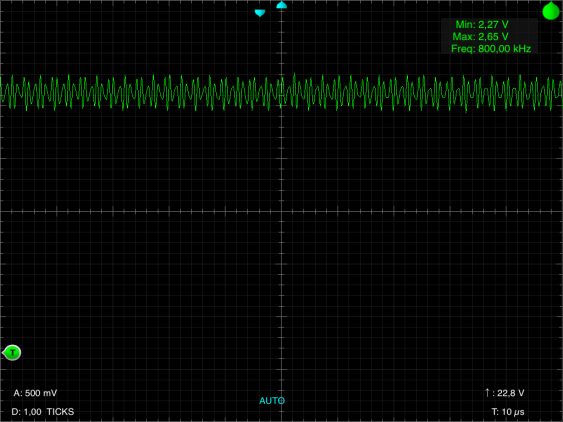
When I zoom a little bit out:
there is still aliasing but at least the signal look strange enough so one might see that there is a problem. But still the scope is limited to signal not faster than 5 MHz, and even then the probe limits its usefulness.
Conclusions
So what did I learn?
On a fast signal the difference between the scopes is quite significant. If the scope (or probe) bandwidth is well above the signal bandwidth it doesn’t matter much, but one wants to have some headroom to see potential distortions (such as ringing on digital signals). Any signal above the specified analog bandwidth gets seriously dampened. That means that e.g. high-frequency ringing or oscillation might just not be visible.
The effect of the probes is not as pronounced, but its still visible. And when the probe bandwidth is to low for the signal, its gets really distorted. And most important - you want to make sure the scope bandwidth is well above the signal bandwidth because otherwise what you see it not what is there.
